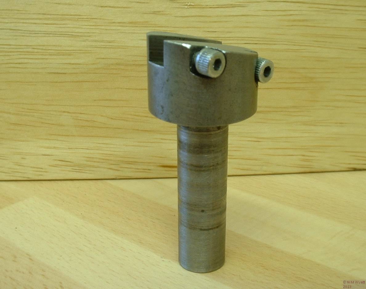
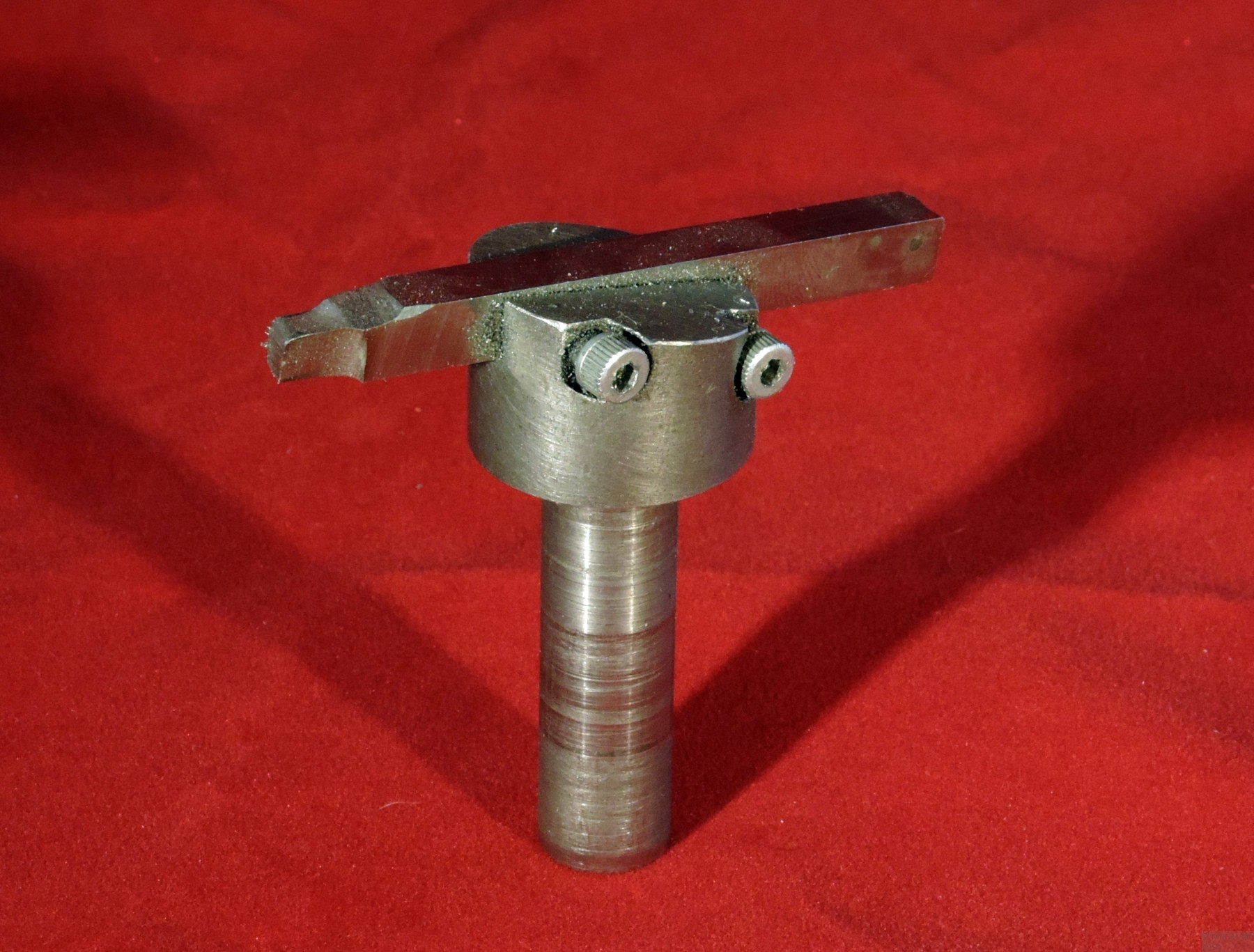
A fly cutter is a single point tool, usually used for machining plane surfaces. It is an inherently accurate tool when used in this way, and if the toolbit is a good one, rigidly held, it will produce smooth, flat surfaces with the most basic of set ups - as long as the mill is correctly trammed (i.e. the column is at right angles to the table). It is also possible to flycut convex surfaces, but the lack of fine adjustment of the typical flycutter imposes limits on accuracy.
There are innumerable ways of making a fly cutter. The basic requirement is simply a toolbit holder, which is easy to attach to a rotary machine such as a lathe or a mill. This straightforward but useful example was inspired by a photo, though many similar ones are manufactured. Stan Bray has described another useful style, which bolts directly to the faceplate. Tubal Cain was unashamedly used a square-section boring bar held crosswise in a chuck!
The body of the cutter is just a piece of 1” mild steel bar, turned down to 1/2” to make a shank. When you hold the cutter in a chuck, the body can be held flush against the jaws, preventing any rearward movement. The thick end of the bar can be sawn and then filed to a 10° angle. This angle gives the toolbit its top relief.
For use with 1/4” HSS tool steel, a slot offset from the centre line of the body is needed. On my mini-lathe I was able to achieve this by holding the shank in the lathe’s tool holder, suitably angled. I cut the slot with a 1/4” FC3 mini-mill, which gave a slot that was good fit for the tool steel. By using the same mill in a pillar drill and ‘plunging’ it into the thick side of the body, two recesses with 4BA tapped holes for the securing screws were easily made.
A simple Fly Cutter
The tricky bit is making a good toolbit. You will need a roughly 2” long piece of 1/4” square HSS. If you need to shorten a longer piece, grind a shallow groove all round with a mini-drill and carborundum wheel. Hold the bar in a vice, covered with a cloth, then tap the end sharply with a hammer. To visualise the shape of the tool, think how it will contact the work as it rotates; with the bit in the holder identify the corner that will do the cutting. The angle of the holder provides one clearance angle, but you need to grind further clearance on the end, ‘front’ and ‘top’ of the bar. Aim for 5-10°, and a little more on the end of the bar. Effectively you need to create a left-handed knife tool.
In use the cutter should be held firmly in a chuck. In the case of milling machines supplied with heavy-duty drill chucks, you can probably get away with holding the cutter in it, but don’t try using the fly cutter in a pillar drill. Fly cutters need to be run slowly; this one has a maximum of a 3” cut and you should run it no faster than you would turn a 6” diameter cylinder - pretty slowly. The work should be moved past the cutter; on smaller lathes it can be a challenge to achieve a set-up where the whole area to be worked passes the cutter. The depth of cut and feedrate should be less than usual, because of the significant leverage between the end of the cutter and the shank. Be patient and keep your cutters sharp and you will get excellent results.
Finally, a version of this tool that is not angled can be used to hold form tools, such as those used for cutting gearteeth or special profiles.

