If you find this website useful, please check out my books or visit my Amazon Author page. Or even Buy Me a Coffee!
Uncategorised
Uncategorised
Over recent years various 3 1/2” centre height “mini-lathes” have become increasingly popular as an entry-point into model engineering. Personally, I don’t like the term ‘mini lathe’ – it suggests that they are toy-like or unsuited to ‘real model engineering’. Fifty or sixty years ago, if you could not afford a large, full-featured lathe one choice you had was a true lathe such as the Adept, Flexspeed or Centrix Micro – each of which could truly be described as ‘mini’ and lacked any screwcutting capability. Even so these lathes were capable of producing superb results in the right hands, and in the hands of some owners were modified to become full featured and true precision instruments.
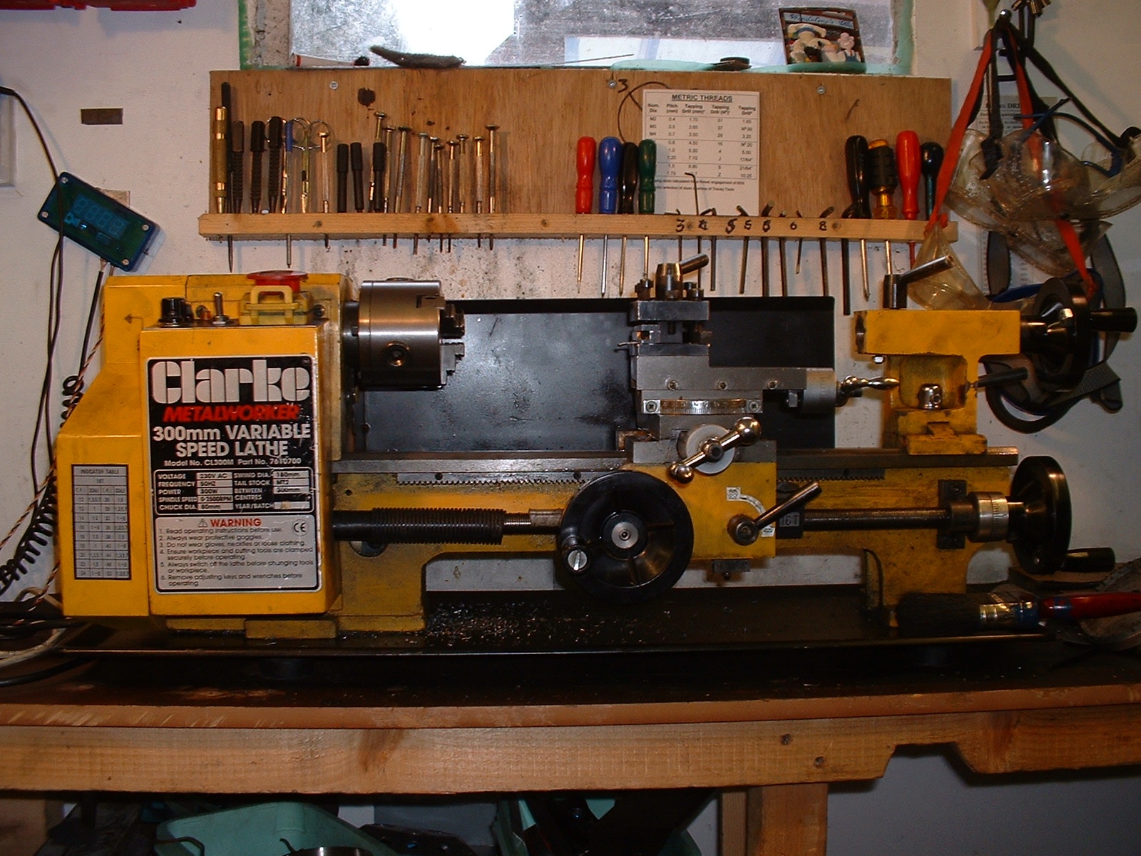
My mini lathe, a Clarke CL300M, taken before the bearing change. At least eight other modifications can be seen in this view!
The modern ‘mini-lathe’ is technically far advanced from these historic examples, though it fills the same niche. It has much greater capacity, a built in variable-speed motor, screwcutting and fine feed, is far more rigid and, with the benefit of modern mass production, is probably more accurate. The one issue that does get raised by users of these lathes, however, is difficulty in parting off. Parting is one of the most demanding tasks for any lathe, as it involves taking a broad cut with an overhung tool, often at the bottom of a deep groove.
You may ask what all this has to do with roller bearings and angular contact? Well there are several requirements for successful parting, and the quality and adjustment of the lathe mandrel bearings are one. Mini lathes are supplied with the mandrel fitted with ball bearings as standard, and for some users these have proven to be a source of trouble when parting off or even, in extreme cases, when trying to achieve good surface finishes. In lathes where these bearings are not up to scratch, changing to roller bearings is an economic and realistic way to address the problem.
See also: Changing the Bearings on a Mini Lathe
But there are many other pitfalls for the careless parter-offer, and unless these are addressed changing your mandrel bearings is pointless, and if they are, you may not find the need to change them anyway. So in this article (sorry!) I will explore the mysteries of parting off and explore the various solutions to allowing our mandrels to rotate.
Perhaps every model engineer wishes to attain LBSC’s nirvana of ‘parting steel with a sound like frying bacon’, but it was the greatly respected George Thomas who made parting off a fine art. He combined a well-adjusted lathe, a rear toolpost, the right tool and the right speed. With a special tool shape he reached a point where he could part off 1 1/2” mild steel at 615 rpm! By his own admission this was a piece of showmanship reserved for exhibitions, and more usually he found a suitable speed (for mild steel) of 200 rpm per inch of diameter.
A well adjusted lathe means ensuring the saddle, cross-slide and top slide all move smoothly, but without any trace of shake or movement. Rock the toolpost and watch anywhere two slides rub together – if you see a bead of oil moving in and out, then they are probably too loose. Make sure there is no play in the mandrel in its bearings. If there is, cautiously tighten the locknuts at the rear of the mandrel.
A rear toolpost, with upside down tool, is widely recognised as improving parting off, by reducing the chance of ‘digging in’. Apparently the rear-mounted tool will tend to spring out of, not into, the work and for materials which produce short chips, rather than curls of swarf, these will tend to fall clear of the cut. I have never seen a completely convincing explanation of the geometry involved, but several respected model engineers have testified to the effectiveness of this approach, and it has been a popular technique since the 1940’s. Mini-lathes do not mount chucks on a screwed mandrel nose and have reversing at the flick of a switch. This means to explore the benefits of this geometry one simply has to invert and pack up a parting tool in the normal toolpost, and reverse the lathe rotation.
George Thomas’ ideal tool had a v-groove on top and the end ground to a v-point, to encourage the formation of curled, narrow swarf (Duplex advised a rounded convex-ended tool for the same reason). I’m sure that both would have admitted that this is a counsel of perfection and that what really matters is a sharp tool with appropriate top rake and adequate front and side clearance. Two essential pieces of George Thomas’ advice, however, are to match the size of the tool to the job and to keep the end of the tool square to the job. Small tools are not rigid enough to tackle large diameters and the angled tool end that avoids making an end pip produces sideways forces that can bend the tool off line and jam the job.
This drawing shows ideal angles for a normal parting tool as recommended by Duplex.
Getting the right speed for any parting job depends on so many variables (the material, its diameter, the tool and the state of the lathe, and some would say the phase of the moon) that there has to be an element of trial and error. The same applies to getting the correct rate to feed in the tool. Fortunately the variable speed control of mini lathes comes into its own for parting – you can gently vary the speed to get the best results, and also speed up as the diameter drops.
Finally, don’t be afraid of the job. A jam up and a broken tool-tip can make you understandably cautious. George Thomas was adamant that a confident and positive approach was essential, and that over-cautious pecking at the work will never bring good results. Don’t just watch either – let your ears and your fingertips tell you what is happening.
A 1940’s article by LBSC advocated a useful tool, not for parting off, but for the similar task of making deep, wide grooves in large diameters. The tool has the shape of a fish’s tail in plan view, the opposite of George Thomas’ tool. I ground a shallow vee in the end of a normal parting tool using a mini drill mounted stone, in order to turn a wide groove in 3” diameter cast iron. I found this shape of cutter was less liable to chatter than a normal parting tool. In use it is fed in five to ten thou at one side of the groove, moved across to the other side of the groove and fed in again before the return journey. The ‘double pronged’ design cuts the full width of the slot to the full depth with ease.
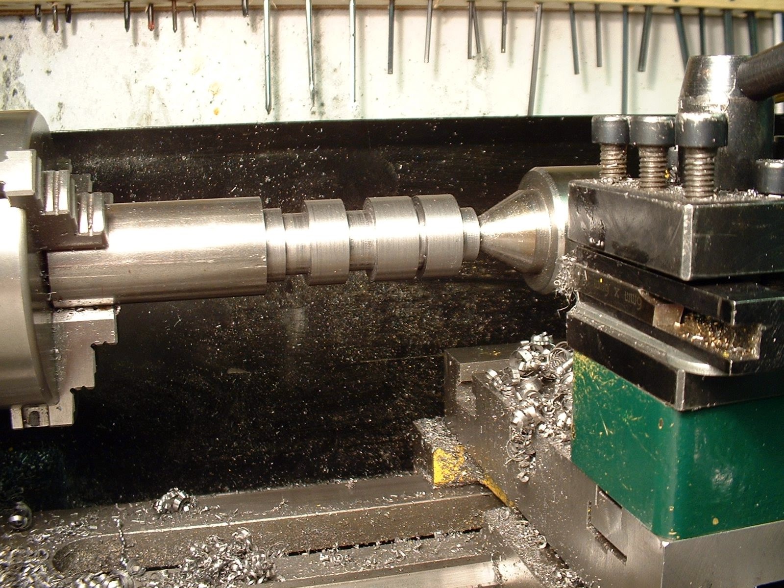
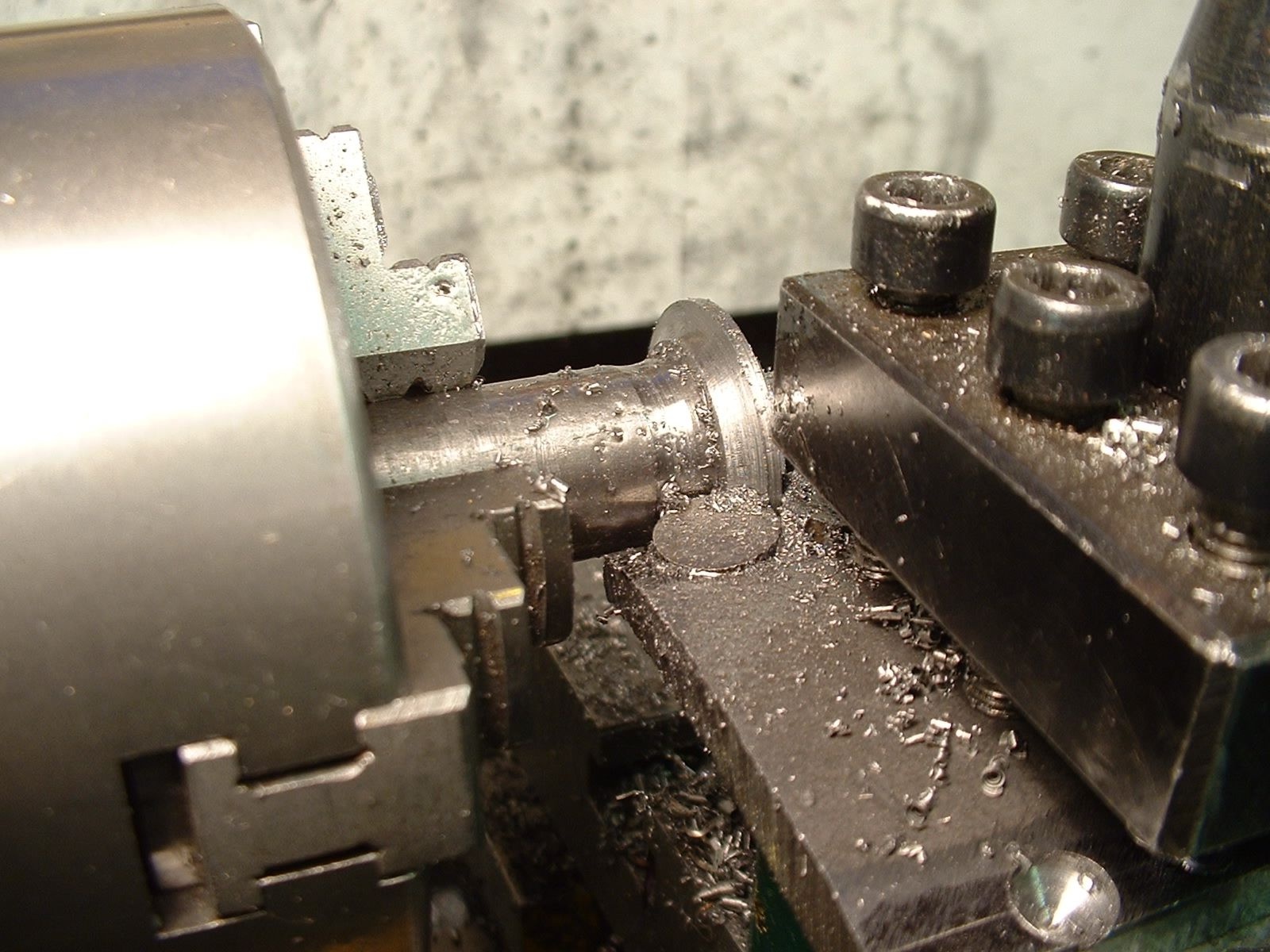
Producing a series of gear blanks in a medium-tensile steel was essentially a multiple parting off operation. Note chatter marks at the bottom of some diameters.
At first I had all the parting off problems recounted by many mini-lathe owners, and had my fair share of ‘dig ins’ and chatter. In time I was able to overcome these by following the above advice. I also found the huge difference made by a brush full of neat cutting oil in the groove. Most of all, I found the benefit of having confidence to feed in and get a positive cut. After a fair share of jams and scrappers, I eventually reached the point where I could reliably part off 1 1/8” alloy steel. With standard bearings I even used a parting tool to cut a deep groove in some (freely machining) 2 1/4” diameter cast iron.
Using a broad form tool, such as when making a gear cutter in silver steel, is possibly one of the few tasks even more demanding than parting off.
Let us assume that you are in the position of some mini-lathe owners, having tried every tip and wrinkle and still not getting successful parting off. The final option is to replace the mandrel bearings in the headstock. There are a number of requirements for lathe bearings. They need concentric accuracy, they must be able to take both high axial loads and thrust loads, they must have low friction and ideally they must have a long life.
Roller bearings are the ideal choice when turning the barrels of a battleship’s 16” guns, simply because of the loads involved, but for small lathes the choice is less clear as almost any type of bearing could be used. Once, many had mandrels running in a plain cast-iron headstock, which is a perfectly good solution with adequate lubrication. Before the Second World War plain and taper bushes and sometimes ball bearings were the rule. Roller bearings were scarce during the first half of the twentieth century, but their use took off during the Second World War. Even so many top quality post-war lathes, notably Myford’s ML7, used plain bushed bearings and a ball thrust bearing, whilst the Super 7 used a hand scraped tapered bronze bush at the head of the mandrel. There is no doubt that these bearings could handle any task within their lathe’s capacity. On the other hand slightly larger lathes, such as those by Boxford and Colchester, typically had roller bearings.
The mandrel of a Milnes Type R lathe, fitted with two taper roller bearings at the front of the mandrel and two further ordinary roller bearings.
At a slightly earlier time LBSC was in no doubt – anything but roller bearings! In one of his “Lobby Chats” he told the tale of new “Type R” lathe he had received in 1923 from Henry Milnes, of Bradford, to replace his 3 1/2” Drummond. If I dare paraphrase a tale he told in his inimitable fashion, it went something like this: He didn’t care for the specified roller bearings, but obtained a written guarantee that, if unsatisfactory, they would be replaced with plain ones. Within three weeks he had detected ‘fine lines” and got onto the maker, who replaced the front bearing with a bronze cone. Another three weeks and the problem arose again, and this time it was agreed to be the fault of the tail-end roller bearing. The patient Mr Milne agreed to supply a specially made roller bearing, but there would be a few weeks delay. Now LBSC depended on his lathe for his living, so the manufacturer sent him a temporary bronze bush, which he fitted, immediately curing the trouble. In due course the new ball bearing arrived, but as the bush was doing fine, he thought he’d keep it for the time being. Some time later, while turning a wheel for ‘Bantam Cock’ on the self-same lathe he started getting chatter marks; inspection revealed a little play in the bronze bush, it had worn just slightly oval. The replacement ball bearings were found to be a perfect fit. The bush was put into ‘honourable retirement’, with due reverence. This story was told in 1946 – the temporary fix had done its duty for over twenty-three years.
A Milnes Type-R 3 3/4” lathe, fitted with lubricators for the mandrel bearings, as used by LBSC for around a quarter of a century (see www.lathes.co.uk for more details of this and other veteran lathes).
So Curly wouldn’t touch a roller bearing with a barge pole, but a year later in 1947 they were stoutly defended in the Editor’s correspondence. E. H. Doughty, British Timken Ltd.’s Chief Technical Engineer, challenged some of the magzine’s responses to queries concerning the rigidity and finish achievable with roller bearings earlier in 1947. The detailed letter included arrangements for four-, three- and two-bearing spindles. The two-bearing arrangement is exactly the type that applies to mini-lathes, and is stated to be ideal for smaller lathes where temperature variations are small. He claimed high precision, robustness, long life, low friction and the potential for high speeds as the benefits of their bearings. Mr Doughty did not agree that plain bearings were preferred by most users, claiming that the use of roller bearings was increasing rapidly both before and after the Second World War. He added that during the war tens of thousands of units gave “every satisfaction” in machine tools of all kinds.
This design for a two-bearing work spindle by British Timken is comparable with that applying to mini lathes.
Another advantage of ball or roller bearings is ease of lubrication. A plain bearing mandrel demands a slow but uninterrupted flow of oil, otherwise rapid wear will soon be apparent. A sealed ball bearing may not expect any lubrication during its normal service life, and even ‘open’ grease-packed bearings need only occasional attention (how often do you repack the axle bearings on your family car?)
Now Curly’s problem was not just chatter, it was also fine surface patterns on the work. Unsatisfactory finish was clearly a concern among likely users of roller bearings. Mr Doughty claimed very fine finishes, even at high production rates. Perhaps a clue to where poor finishes arose is given by his explanation of the need for no or minimal preload. Apparently the popular impression was that a fair degree of preload was necessary, generating excessive friction. I imagine the ‘wedging’ action of taper roller bearings makes them easier to overtighten than angular contact ball bearings, and that one symptom of this might be a poor finish. Another one-time Timken employee - ME Technical Editor, Neil Read, pointed out that in 1923 LBSC’s roller bearings would have been made to standards of fit and finish far from what we might expect today.
Whilst there is no doubt that plain bearings can give excellent results in small lathes, most modern small lathes don’t use them because of cost - ironically the relatively complex ball bearing is a mass-produced article. It is considerably cheaper than a tapered phosphor bronze bush – particularly a skilfully hand-fitted one. Our economically priced mini lathes use this cheapest option – ball-races.
Mini Lathe Bearings
Ball races offer only point contact, and in theory even if perfectly adjusted they are inferior to taper bearings (whether plain or roller), both of which have a far greater bearing area, promising greater rigidity and accuracy. Because of the arrangement of the headstock a plain bearing is out of the question for us, but roller bearings are only about 50% longer than an equivalent ball raced bearing, and we can squeeze them into the space available. The standard (ball raced) bearings fitted to mini-lathes are pretty hefty units, and able to take a considerable load. I understand, however, that depending on the source of the bearings on any particular unit, you may get ones made to different specifications. Certainly a proportion of mini-lathe owners report persistent problems with surface finish, chatter and particularly with parting off. If we accept Mr Doughty at face value, those with these problems should be able to solve them by fitting taper roller bearings and possibly improve the rigidity and accuracy of their machine to boot. Certainly there are an increasing number of mini lathe owners who have either carried out the ball to roller conversion, or who are contemplating it.
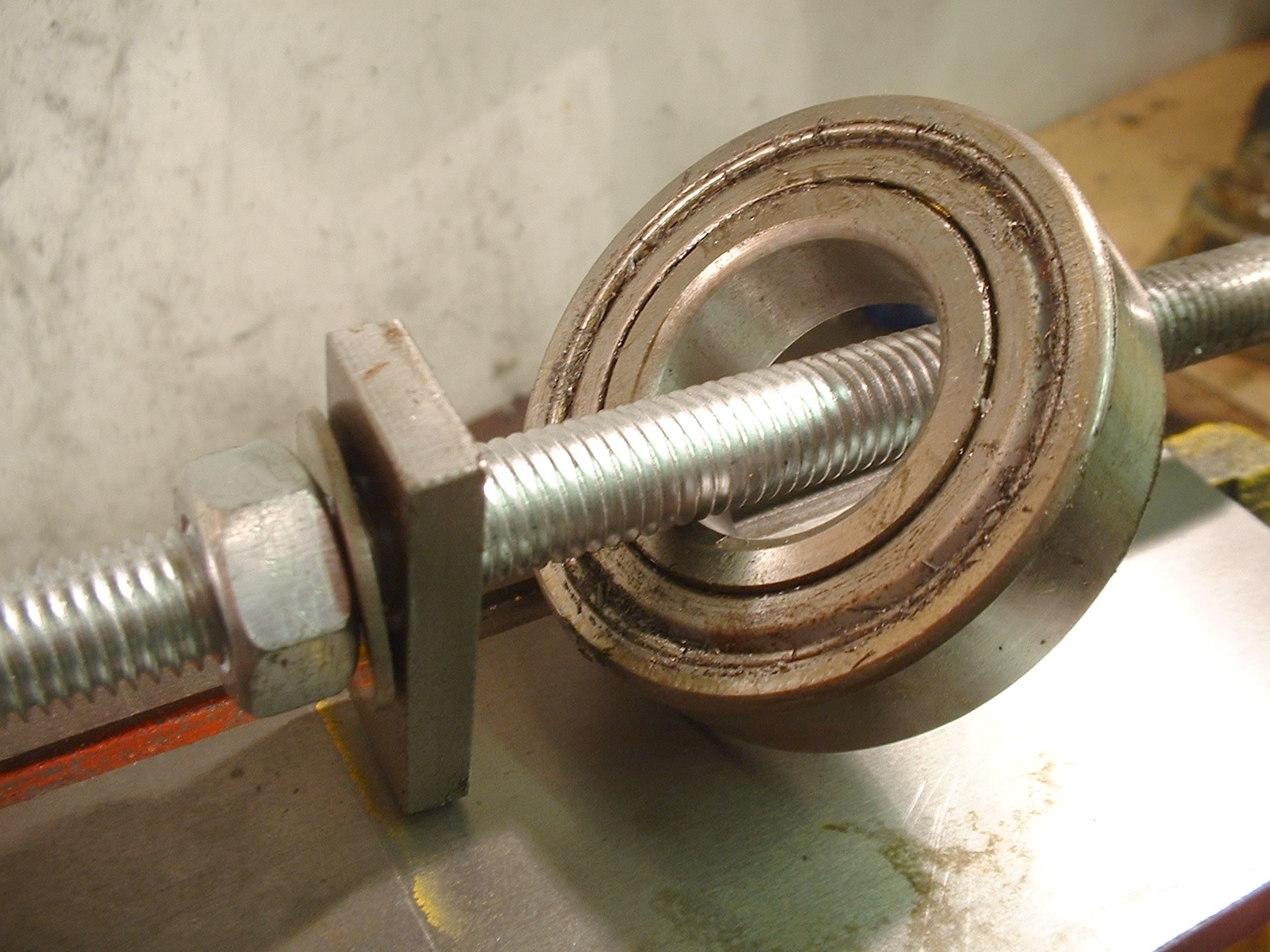
The original rear ball raced bearing removed from a mini lathe.
For a mini lathe where loads are much lighter and the motor is less powerful, another option is to fit angular contact ball bearings. These share the benefits of better control of end loading while being better suited to high-speed use; they also can by exchyanged for standard bearings with no dimensional changes making coinverion rather simpler.. They have become increasingly popular as a choice of mini lathes.
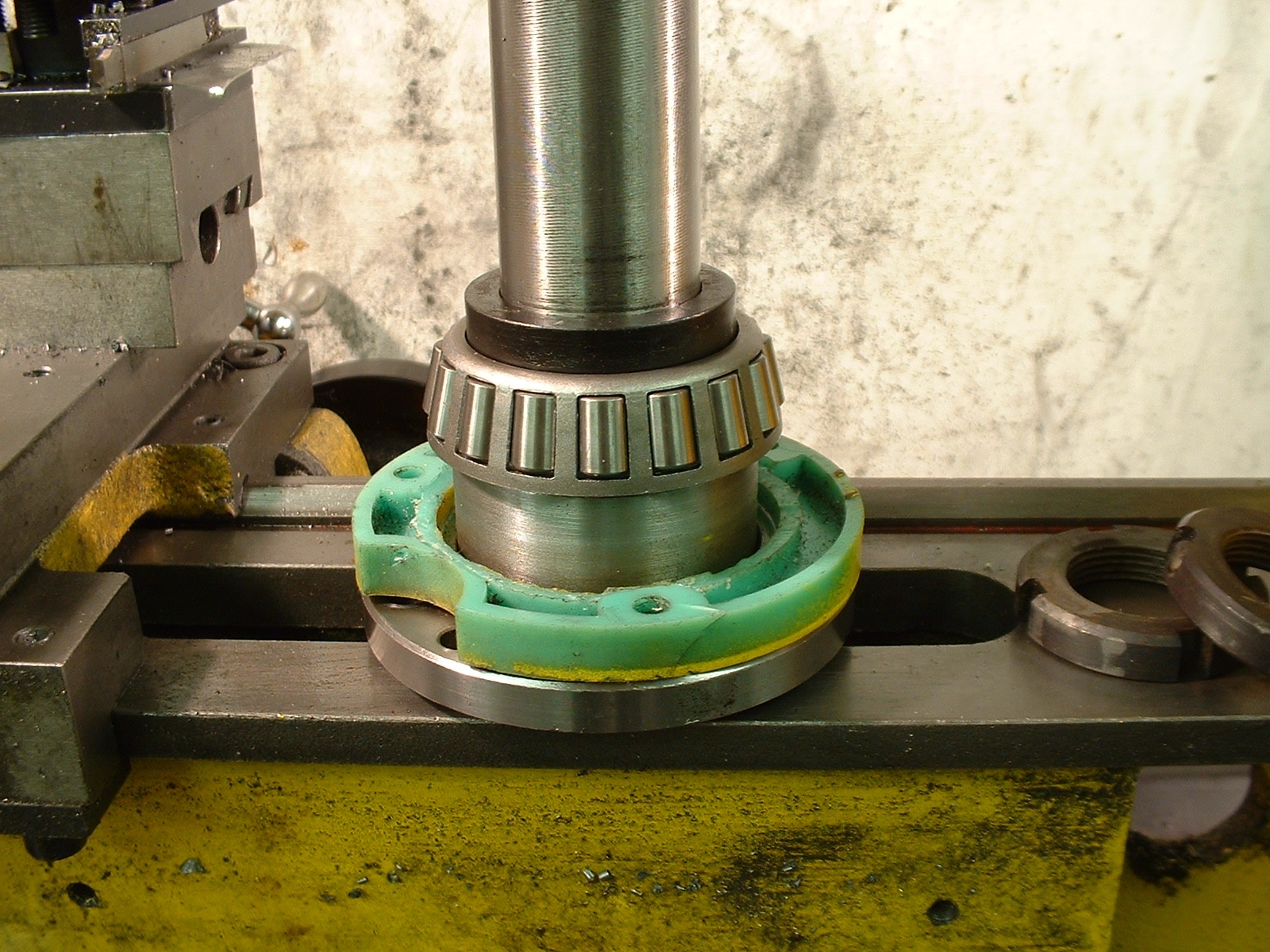
Replacement front inner race with its caged rollers fitted to the mandrel of a mini lathe (together with the front bearing shield and a short spacer).
All of which begs the obvious question – if it ain’t broke, why fix it? I am another traveller on the endless quest for the ‘ideal lathe’. Adding roller bearings would not harm my lathe, and unlike roller bearings, I gain some real control over the bearing adjustment. If they gradually wear, I can take it up properly.
In a second article I will describe my experience in fitting roller bearings to a Mini Lathe, and give my assessment of the effect they have had on the lathe.
See also: Changing the Bearings on a Mini Lathe
- Details
- Category: Uncategorised
First, a caution! These tips were written for the Clarke CL300M, as it was supplied around the turn of the century, and after I had been using it for three or four years. Since the CL300M came out, huge improvements have been made to the basic Mini-Lathe design with everything from quick-release tailstocks and brushless motors. Nonetheless, many of these tips still apply and others will be of use to people who have acquired second-hand mini lathes.
The lathe has given me 20 years of service, and is probably one of the most modified mini-lathes on the planet. It now plays backup to my much larger Arc Euro Trade SC4-500, but still gets used. My thoughts on some of the issues below have moved on, see my comments in square brackets.
For a fuller guide to mini lathes see my book The Mini Lathe.
1 20% Extra Free!
You might imagine that the limiting factors on cross-slide travel are adequate engagement of the feed nut and the dovetails. This is true when feeding the slide inwards ‘away from the operator’, but it is possible to increase the outwards travel significantly. In fact, you can increase the usable travel from 2 1/2” to over 3” with two minor modifications. Firstly, the slide itself butts up against the index. Milling a shallow recess to clear the index is the first step. The second is to file the end of the feed nut to a radius of 3/8”, so that it can feed right up into the end of the slot in the saddle. Chamfering the bottom edge of the nut should ensure you get the last thou of full travel. This is quite a bonus, as it enables you to face work a full 6” in diameter, as against 5”. I have only made this modification to my new t-slotted slide [do this mod! It's the best one there is for any mini lathe].
2 Tools
The toolpost of the lathe is such that 5/16” square HHS toolbits can be used with no, or very little, packing (depending on how they are ground). This is a common size, but surprisingly, no tools of this size are to be found in the set marketed for the lathe by Clarke.
The set of tools supplied for use with the CL300M comprises a set of small 6mm square tools and a holder, and one big tool - a hefty double-ended bit in a robust holder. The holders are such that the tools come to centre height when in the toolpost. The larger tool is the only one in the set capable of cutting into a square corner. It can also be used for making 45-degree chamfers, but it is rather peculiar, apparently suited to very heavy work, and one I have hardly used.
Of the smaller tools, the finishing tool is acutely pointed and needs the end stoning to get a good finish, but its shape is such that one sharpening and it’s almost useless. It’s too acute to serve as a proper thread cutting tool. The handed roughing tools are better, as they can be sharpened by grinding the flat side of the tip, but they cannot cut into a corner. Finally, the parting tool works well, but is difficult to sharpen and keep the right top rake. The best part of the set is the holder that allows one to use 6mm square tools without packing. Pre-ground 6mm tools in various styles are readily available, and can be very useful for smaller work –especially very narrow parting tools. The smallest ground HSS boring bars fit neatly into the holder. In the end, however, I have turned all my tools around and ground the blunt ends into new tools – thread cutting, knife and parting.
Aside from a 1/16”-thin parting tool, most of my machining is done with very simple tools ground from 5/16” square HSS [these days I prefer indexable tungsten carbide tooling, but HSS is the easiest option for beginners being easier to use]. This generally arrives with a chamfer on the end that is a good starting point. I use a simple rest on the grinding wheel and put on top-rake and front clearance aiming to grind right up to the corner of the bar, then take an angled skim off the end to leave a sharp point. For general use I polish up the edges and round the tip off with a slipstone. These tools cut up to a shoulder and can be used for both roughing cuts and facing at the same setting. For finishing cuts I put a small flat parallel to the cut on the end. I also have a tool of this kind ground to a about 1/16” radius, for rounding internal corners.
In use, the tool is set at an angle, to give suitable clearances front and side. Though tools of this design are often recommended, it is rarely pointed out that, though meant for left hand cutting they can be serviceably used for facing without being reset. I find I have to use a thin alloy shim to pack up the tool to get it exactly on centre height.
Parting tools are best ground by copying a bought one. Sharpness and getting the tip accurately at centre height are the critical issues, as long as there is clearance on all sides and some top rake the exact amounts are less important.
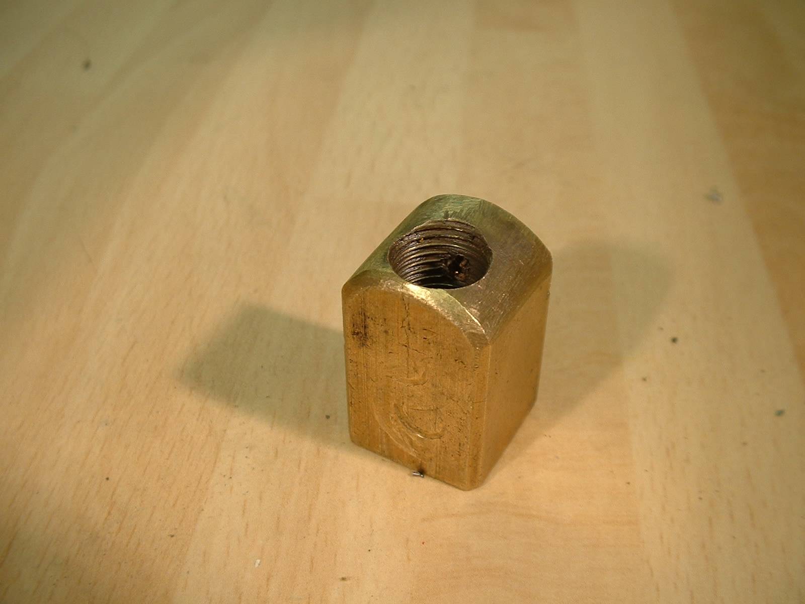
3 The Boring Bit
Say you need a small boring tool, one that will enter a 5/16” hole. One solution is a d-bit style cutter held in a boring bar holder, but I chose to use the rather scruffy device shown in the photographs. This tool is the cranked shank-end of a broken drill bit, held in a drilled-out and squashed piece of aluminium shelf support. Not very glamorous, but effective. In theory the shank of twist drills is rather soft, but I find that this tool happily keeps its edge cutting ordinary steels and cast iron. A more elegant solution would be to make a similar tool from silver steel, fitted in a ‘proper’ holder [I still have and use this ridiculously crude tool!]
Cut a two-inch length of 3/16” diameter silver steel. Smear it with washing up liquid (WUL), then heat it red-hot and allow it to cool slowly. A gas blowtorch is fine for this job, but placing the piece on a small insulating tile will make this much easier. Using a vice and a large pair of pliers, or even a hammer, put a 20-degree crank near the centre of the bar. Now grind away the tip to the profile shown in the drawings. It is important to grind under the cutting edge so that the cutter does not rub when being used in very small holes.
Smear with WUL once more, and heat to red-hot for a few minutes, then quench in lukewarm water. The regularly recommended ‘cherry red’ is hard to judge, Peter Wright’s ‘boiled carrot’ is less ambiguous, I think this is the point when the glow starts to appear to come from within the metal, rather than on it. The mediaeval Japanese artisans who forged a Samurai’s katana matched the colour of the metal to that of the setting sun.
Clean up the piece with emery paper or scotchbrite pad (this is so much easier if you use the WUL!), then temper it by heating the shank until the tip becomes a straw colour. With a small item like this, it is easiest to place it where it can rapidly be poked into a water filled container using pliers, as soon as the colour gets near the tip.
Make a simple holder from piece of scrap square bar that will fit the toolpost. If you drill a 3/16” hole in the holder when it is in the toolpost, then the tool will automatically set itself at centre height. Make another, threaded, cross hole for a suitable screw to hold the bit in place.
4 To Mount or Not?
Large lathes are normally rigidly mounted; either to the bench or even physically bolted to the floor. Small lathes such as the Peatol or Unimat 4 may be free standing or mounted on a baseboard solely for convenience.
With a mini-lathe we have a genuine choice. There is no absolute reason why the lathe should be securely mounted, as long as it is in no danger of moving when in use. If the lathe is used in part of the home, it will be a lot quieter sitting on its built in rubber feet, than bolted to a rigid bench. Furthermore, as long as the bench below is reasonably flat, the lathe be should retain its accuracy. The need for careful levelling and adjustment necessitated when the lathe is bolted down is avoided. I have never bolted down my lathe, and have never had any problems with movement or noise [I never did get around to mounting the mini lathe].
5 The First Cut is the Deepest
Faced with my first lathe, I could only twiddle for so long! I bought a set of hss tools with the machine, so I had to cut metal. This was before I had such useful books as Tubal Cain’s Model Engineers Handbook and Peter Wright’s Model Engineering – A Foundation Course. The only clue I had was the handbook which suggests limiting cuts to a depth of just 10 thou (0.25 mm). Experience has shown that you can take significantly heavier cuts, easily up to 80 thou in soft metals, and 20 in mild steel. The potential of the CL300M is even greater, after fitting a t-slotted table so that the top slide could be eliminated, I found that I could take 1/16” (over 60 thou, 1.5 mm) deep cuts in mild steel, though the finish was a bit rough. The load on the motor for this is considerable, and ought really be reserved for lathes which have had a larger, variable speed AC motor fitted [since fitting taper roller bearings and fitting a3-phase motor with an inverter, finish is fine at 1.5mm deep and I can take 3mm deep cuts]. At this point I ought to recount a cautionary tale!
6 Keep Your Cool
When making the spindle for a rotary table out of a chunk of 3 ½” cast iron bar, the lathe was happily making cuts that just got deeper and deeper (I had an inch of metal to remove), at modest rpm. The spray of iron filings got higher, and I grew dirtier. Unfortunately the power needed for the job made the motor run hot, but the low speed limited the effectiveness of its cooling fan. A loud pop followed by a cloud of smoke announced the failure of two windings in the armature. I found myself inside a Chuck cartoon!
The quotes I had for rewinds were astronomical. Having wound transformers in the past, I considered rewinding the motor myself, but a 240V DC motor has a lot of potential for disaster if wound wrongly, so I decided to seek a replacement.
I won’t tell the whole story of how I tracked down a replacement motor. Suffice to say that one from Clarkes/Machine Mart would have involved a very long wait for a slow boat from China. I could not track down an off the shelf replacement – some washing machines used to use similar motors, but these seem to be obsolete. The various other suppliers of the CL300M and its look-alikes were very helpful, but reluctant to sell me one, as they all had only one or two spares which they (reasonably) wanted to keep for their own customers. Eventually one relented, ‘against his better judgement’.
This exercise revealed some of the differences between the various mini-lathe lookalikes! It also highlighted the excellent service from several of the machinery suppliers advertising in ME – every one I contacted was helpful, despite the fact I had bought my lathe elsewhere. Perhaps the most gratifying aspect of taking up model engineering has been discovering that old-fashioned service and courtesy aren’t dead! Whether I have been buying an expensive gadget, a set of castings or just bits and pieces, I have yet to find a specialist supplier, large or small, who has not spent some time making sure I get what I need and avoid expensive mistakes. Of course the side effects are that a) I usually buy something else as well, and b) I go back to them. If you are in the market for workshop equipment, even ‘cheap’ models, my advice is to contact a selection of ME advertisers and seek their advice, you won’t regret it.
One interesting pieces of advice was the suggestion that I fitted an ordinary AC motor, on the grounds that the lathe was robust enough to take a much more powerful motor. As far as I can see there are a couple of problems with this, but they could be solved. The first is linking into the drive train. This would have to be by belt to a pulley on an intermediate shaft set where the motor is. Secondly, the back gear has roughly a 2:1 ratio, much smaller than most lathes, so a conventional set of coned pulleys would not give a very broad speed range. There would have to be a decidedly Heath-Robinson collection of belts and pulleys hanging off the back of the headstock, and speed selection could be a bit of a nightmare. The easiest solution, would therefore appear to be using a larger AC motor, say ½hp with electronic speed control. This would give a powerful and flexible machine, while remaining reasonably compact [In the end I fitted a 1/2 HP motor and eventually moved on to a three-phase motor and inverter package, which made the lathe an absolute joy to use].
7 Keep Under Cover
The gear cover of the CL300M is held in place by two bolts. Continually removing and replacing these bolts is tedious, and eventually the temptation is to operate the lathe with the cover removed. It takes only a few minutes to drill and tap a pair of holes in the reversing gear mounting plate, fit two screws in place and cut two matching slots in the cover. It now takes only a second to fit or remove the cover. For full details see Mini Lathe Gear Cover Mod [again, this is a mod that every mini-lathe owner should make].
8 Do Blow a Fuse
Buy a few packets of 1.6 Amp quick blow fuses, a pack of ten is pence from Maplin or similar. It is easy to damage the motor of the CL300M if it is stalled for any length of time and a packet or three of fuses are a lot cheaper than an armature rewind or a new motor. One reason long, slow jobs with heavy cuts can overheat the motor, is the reliance on a fan on the armature for cooling, which is ineffective at slow speeds. The constant torque circuitry does a good job of keeping a steady motor speed when running slow on heavy loads, but this creates the illusion the machine can cope with jobs strictly beyond its capability, or at least that of the motor. Always use ‘low’ gear unless you want an extra fast cut as this doubles the motor speed, reduces the load and makes more torque available for cutting. The correct rating of fuse is your best protection against overloading the motor in this way; when I blew my motor, I had fitted a larger fuse.
Treat the electrics of the CL300M with extra respect. The motor runs off some 350 volts direct current (essentially rectified mains). DC shocks are more severe than AC shocks, so it is more dangerous than the mains. Unless you really know your electrics, don’t go exploring in here, and get any problems which arise sorted out by a competent electrician.
9 Sudden Halts
A sudden loss of power accompanied by a ‘screeching’ sound probably means the motor has shifted on its mounts, loosening the toothed belt. A milder scraping sound may mean the toothed wheel has shifted on the shaft, and the belt is rubbing on the guard. In both cases switch off and adjust and retension the belt.
A complete loss of power without the dramatic sound effects could be the shearing of the key in the glass-filled nylon toothed wheel on the end of the motor. This happened to me early on, after leaving the auto-feed in gear when parting (OK that’s pretty stupid, but let him who is without sin cast the first stone!). I filed a groove inside the damaged wheel, to match that on the motor shaft. I then fitted a small brass key between wheel and shaft and have had no more problems [keep an eye on this wheel - if you get a lot of slippage it can wear badly but they are cheap enough to replace].
Since writing the previous paragraph I have discovered another failure mode! The sudden onset of rather rough running with a tendency for the motor to stall and blow a fuse perplexed me, as the job in hand was well inside the lathe’s capacity. All was explained when the drive belt, which had split and was skipping a few teeth, stalling the cutter, finally gave way completely. The only answer is a replacement belt, but these are cheap and off the shelf items from the lathe supplier’s spares department.
10 Lubrication
There do not appear to be any points for oiling the mandrel and other bearings inside the headstock. Does this mean they are ‘sealed for life’, just like the suspension ball joint that seized with the result that the front wheel disappeared into the wing of my car going around a roundabout. An advance over the screw and thread arrangement on my old Marina, I suppose? I worry about this, and fancy the headstock gets a bit warm at times. Several sources suggest replacing the headstock bearings with taper roller bearings. As I have no problems at the moment, I shall leave this job until I do [I did indeed fit roller bearings to the lathe and felt it greatly improved the lathe. Looking back I suspect some of the improvement was the extra confidence it gave me].
An important task is keeping the lathe bed and the various slides oiled. I think a major coolant system for the CL300M is a bit over the top, so I just use neat cutting oil for drilling and reaming, and whenever it seems it may help. The nylon change gears ought to run dry, but as some are metal I slop a little oil about here as well. Keep the leadscrew’s end bearings oiled. There is a nipple at the tailstock end, and a simple hole at the headstock end, but the latter is usually covered by the end cover. Don’t forget that the split nut on the leadscrew takes some of the biggest loads, so keep the leadscrew clear of swarf and well lubricated. Finally, chuck scrolls and adjusting screws deserve a little attention too!
11 Leadscrew Handwheel
In Model Engineer’s Workshop (issue 91, July 2003) Alastair Sinclair suggested fitting a leadscrew handwheel to the similar Chester Conquest. By using a matching wheel to that fitted to the saddle and tailstock, his approach gives the appearance of an ‘original part’.
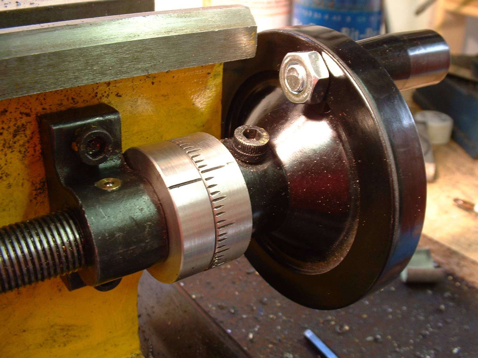
I essentially followed his design, thinking the addition would be useful. In fact, I have found it to be indispensable, using the leadscrew instead of the top-slide or saddle handwheel for almost all manual adjustments or cuts. My major difference was that I have an Imperial 16 tpi leadscrew, he has a 1.5mm metric one. I considered various divisions for the index wheel and settled for 64. This gives evenly spaced divisions for fractions down to 1/128” and beyond, and each single division equals 0.001024”, close enough to a ‘thou’ for most purposes. I was tempted by 60 divisions, which would have allowed the divisions to be grouped in fives, while allowing accurate fractions down to 1/64”, but this way each division would be just 0.000960”, over twice the error of 64 divisions. Both 62 and 63 divisions would have been more accurate, but they are awkward to subdivide. Alastair pointed out to me that a metric leadscrew with an index using 60 divisions would give 1 division equals 0.001016”!
12 Power Cross Feed?
Alastair also suggested using a hexagon bit in an electric screwdriver to give independent power feed to the lathe’s leadscrew. This idea can be extended to the top and cross-slides. Even if you can’t feel any slack in either of the slides, try this. If you keep the speed down you may be surprised at the improvement in surface finish.
13 Ball Handles
The ball handles have thick chrome plate. To avoid blisters I often use a short section of copper or brass tube as a sleeve, when continually winding the cross-slide in and out. I don’t know If this was a contributory factor, but the chrome plating lifted and I ended up with a nasty, deep cut in both thumb and forefinger. The lifted plate, being harder than the underlying steel, wouldn’t file to a smooth finish, so I had to order a replacement handle I have it in mind to replace the ball handles with either solid brass or sleeve and pivot handles [I ditched the copper tube and the replacement handles are still going strong].
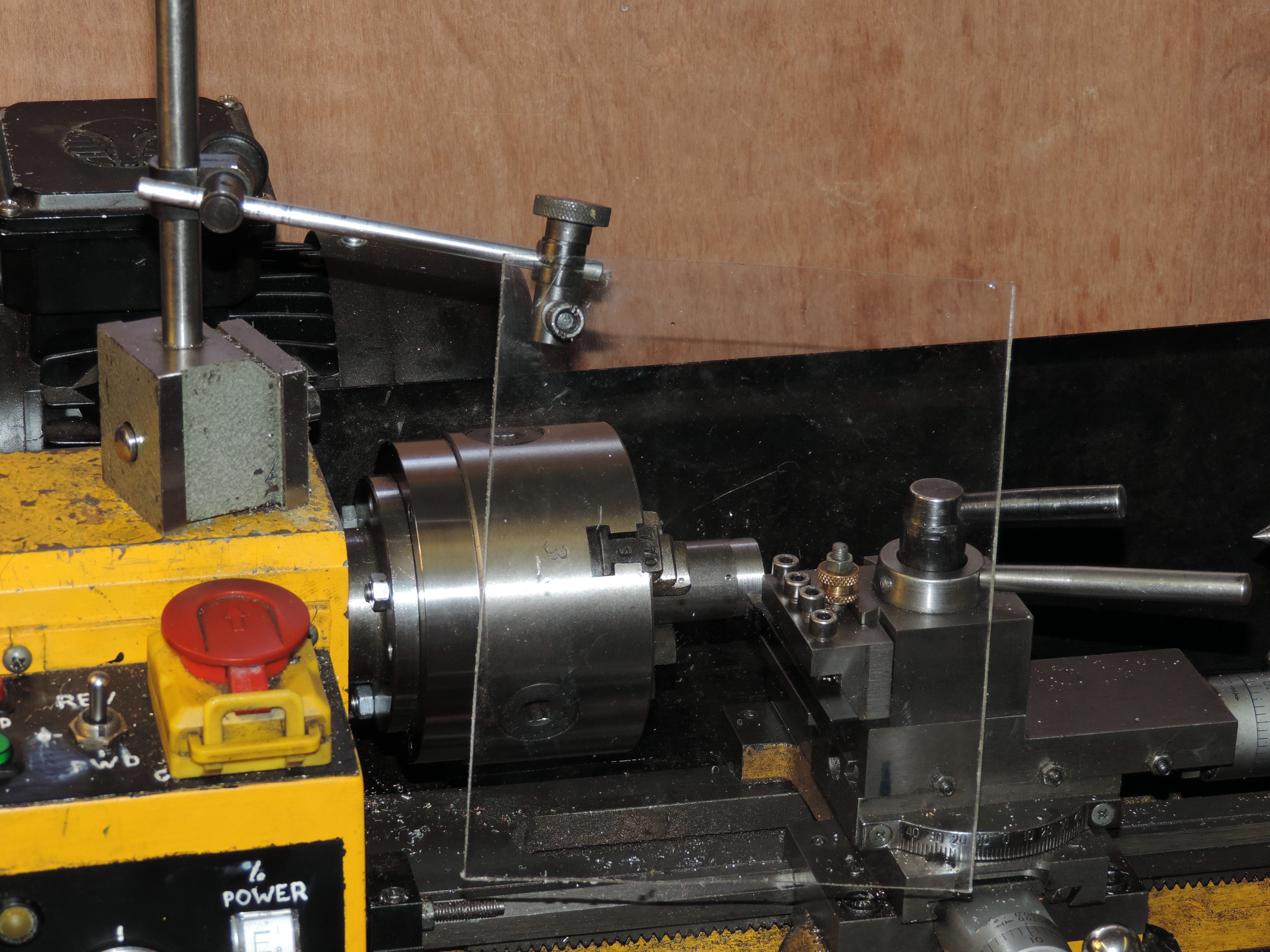
14 Chuck the Guard?
The chuck guard only obscures the part of the chuck furthest from stray fingers. I confess I have removed mine, as it constantly rattled on the chuck, but sensible advice is to replace it with one that reaches around the front of the chuck, like those fitted to many larger lathes. An alternative is a large sheet of acrylic or (ideally) polycarbonate some 3-4mm thick, suitably mounted, which can act as both safety screen and swarf deflector, arranged to swing in front of the lathe.
15 Fitting Chucks and Faceplates
If you want to fit a faceplate or a four jaw chuck, the fitting is for a standard 63mm register with three or four bolt holes. No separate backplate is required, and the arrangement has the advantage that reversing the lathe won’t loosen the chuck. The typical diameters are 80mm for the chuck and 7” for the faceplate, but I understand that some 100mm chucks will fit the lathe without an adapter. Don’t be surprised when you find that these are supplied with 6mm bolts that you can’t fit behind the backplate! All you have to do is a quick hacksaw job and convert them into 6mm studs. Loctite these ‘studs’ into the threaded holes in chuck or faceplate. I used the bolts supplied, as they were of good quality. They have not suffered from repeated retightening, though I have replaced the relatively soft nuts several times.
Never use the reversing switch when the motor is turning. The best possible result is a blown fuse [more modern versions have more robust electronics and motors, but please treat them with some respect!]
16 Parting is such Sweet Sorrow.
My top tips for easy partings are:
- A sharp tool at exactly centre height.
- Part as close to the chuck as possible, and minimise overhang of the tool.
- Start with a slow speed and feed the tool in gently, but firmly.
The variable speed control of the CL300M comes into its own for parting – you can gently vary the speed to get the best results, and speed up as the diameter drops. Don’t just watch – let your ears and your fingertips tell you what is happening.
Returning to that rotary table spindle for a moment, it required a very deep, wide groove. I cut this using a special design of parting tool, gleaned from a 1940’s article by LBSC. The tool has the shape of a fish’s tail in plan view. I ground the shallow vee in the end using a mini drill mounted stone. This shape of cutter is less liable to chatter than a normal broad parting tool, and is also capable of taking light cuts on the side. In use it is fed in five to ten thou at one side of the groove, moved across to the other side of the groove and fed in again for the return journey. The ‘double pronged’ design means that the tool cuts the full width of the slot to the full depth, with much less tendency to chatter.
17 Fix that Sticky Index
Does the index on your top-slide stick when you wind it out? Well take it apart and you’ll see why – it’s used as a thrust bearing against the stationary index! (I understand this may not be the case on some other ‘brands’ of mini lathe. I solved this problem by making a thrust block of 7/8” of 1/4” by 3/4” mild steel bar, bored 10mm to take the leadscrew, with the hole suitably chamfered, and screwed to the back of the stationary index wheel with two 4BA screws. I then skimmed a 1/64” counterbore on the index wheel, and put it all back together. This simple arrangement also allows considerable reduction of backlash, just leaving that of the leadscrew in the topslide block itself, for the loss of perhaps 1/8” of travel [this 'design error' certainly seems to have been addressed in most modern mini lathes].
18 The Last Splash.
The large black splash guard on the back of the lathe can be both a help and a hindrance. It reduces the travel of oil and swarf across the workshop, but also reduces the travel of the cross-slide and gets in the way if you need to remove it. The guard appears to be held on by 2BA, rather than M5 bolts. I cut short sections of 2BA studding, and fitted knurled brass thumbwheels on them with a drop of cyanoacrylate. Instead of trying to poke an allen key into a hidden screwhead, I can now fit or remove the guard in seconds [oh yes! Do make this simple time saving mod].
First a brief digression – these pages have seen many argue the case for metric or Imperial. Well, my generation was in school during metrication, so I was taught Imperial and CGS metric. Since then ISO metric has taken over, and those who decry Imperial measure ought to contemplate how the inch has outlived the centimetre! Having the whole lot turned upside down while young enough to cope leads to a sort of dimensional bilingualism. Even so my mother tongue is Imperial and if something scares me I run a mile, not 1.6 kilometres, thank you. (How many readers remember the red ‘Sylvine’ exercise books, with a wonderful table of rods, poles, perches and the whole heavenly host of Her Majesty’s measures?) But to get to the point, tools are expensive, so I get the most cost effective solution. This typically means BA threads for small sizes and metric for larger ones.
If a completely separate, low voltage, supply is available it is possible to add a small fan, such as you find on computers, set to blow cooling air through the motor. This will help considerably at low speeds. Make sure you arrange it to assist, not fight, the airflow generated by the motors built in fan when it runs forwards. I assume that you will make very little use of the reverse direction of the lathe – just running a thread back out of a die or similar. If not, you will need to switch the fan off when you run the motor backwards. It has also recently been suggested that a fan could be fitted to cool the motor control circuitry. I am considering moving the control circuitry into a separate box, and adding various other items, including a tachometer, temperature monitoring and an ammeter to monitor the motor load [I never added teh fan as I changed motor drive, some have found adding one useful].
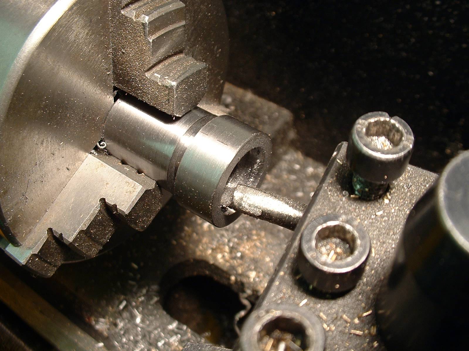
19 Fly Cutter.
This simple fly-cutter is copied from an example by John Rinaldi, and is turned from a section of 1” bar. The shank is turned down to an accurate 1/2”, and the end cut across and filed flat at an angle of about 10°. Of course, if you had a fly cutter, you could use it to do this job… Mount the embryo cutter in the toolpost, by gripping the shank (use
some shim to protect the shank), it will be at the correct height for the slot to be milled out using a 1/4” end mill.
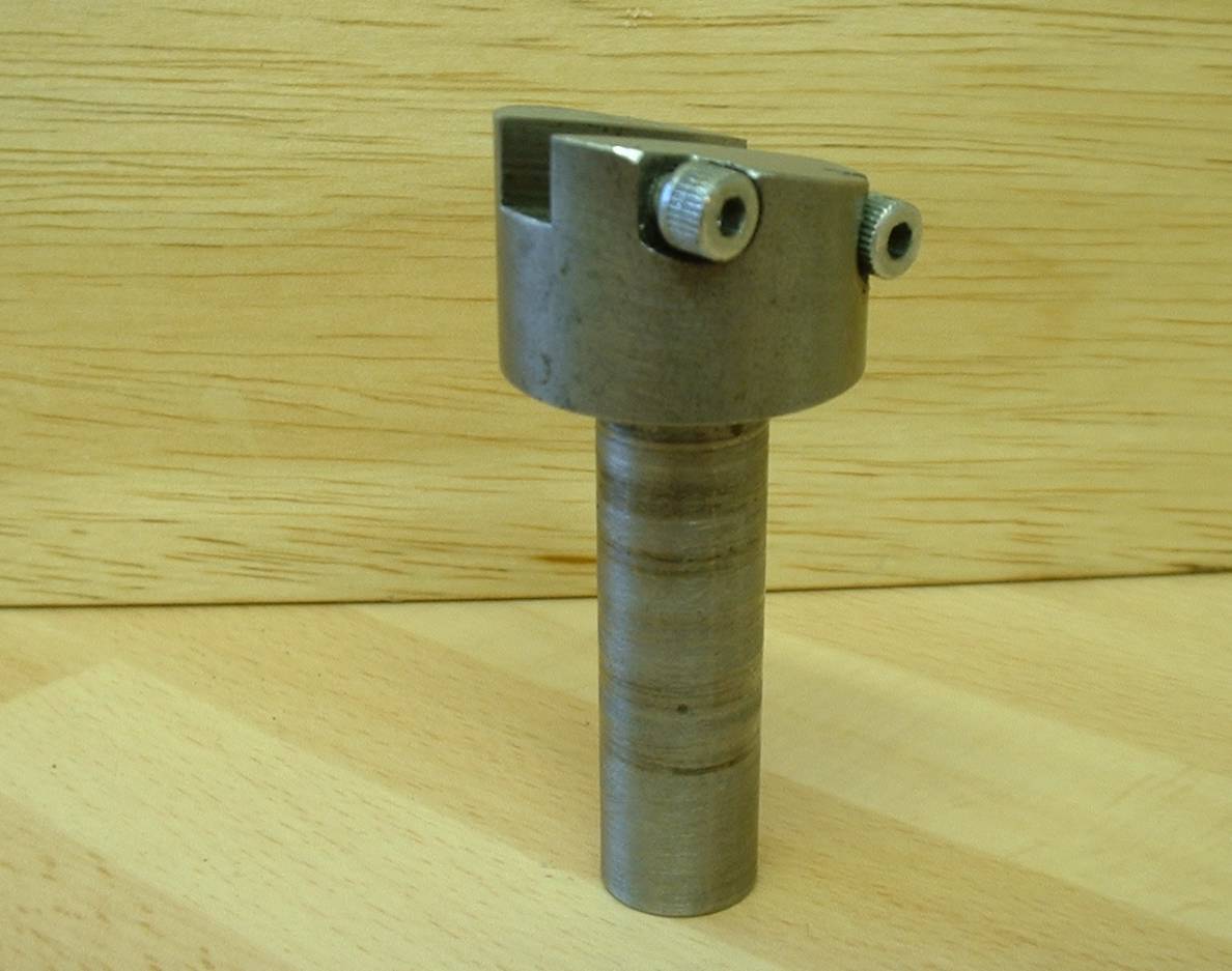
Once you have the slot finished, rotate the tool body and ‘mill’ two rebates for the holding screws using a drill press. If you use a slot-drill or FC3 ‘throwaway’ cutter you will find that, as long as the work is held rigidly, you can gently plunge in the tool this way, as you are not feeding the work from the side. Drill and tap the holes for the screws, and tidy up the job with a fine file.
The bit I use is just a simple knife tool ground on the reversed end of a commercial 6mm square HSS toolbit. Never forget when buying a ready ground tool, that it comes with a ‘free’ do-it-yourself tool at the other end! I grind exactly the same shape and clearances as I would for a general-purpose lathe tool, and it seems to work perfectly well.
To conclude
The mini lathe of 20 years ago was an affordable introduction to turning, but had a number of weak points - chiefly the vulnerability of the motor and control system to abuse. If you go for a top of the range modern mini-lathe you are getting a remarkably capable machine that addresses many, if not all, of the issues I mention above.
- Details
- Category: Uncategorised
The gear cover of the CL300M and other mini lathes is held in place by two bolts. Continually removing and replacing these bolts is tedious, yet the temptation to operate the lathe with the cover removed should be resisted for (hopefully) obvious reasons. In past issues of MEW two solutions have been offered – both involved replacing the M5 cap screws with an easier to release alternative. However, these ideas still mean having to undo screws, and there remains the risk of losing a fastener in the swarf or under the bench!
May I suggest an alternative approach? It is literally a ten-minute job to perform an instant-release modification.
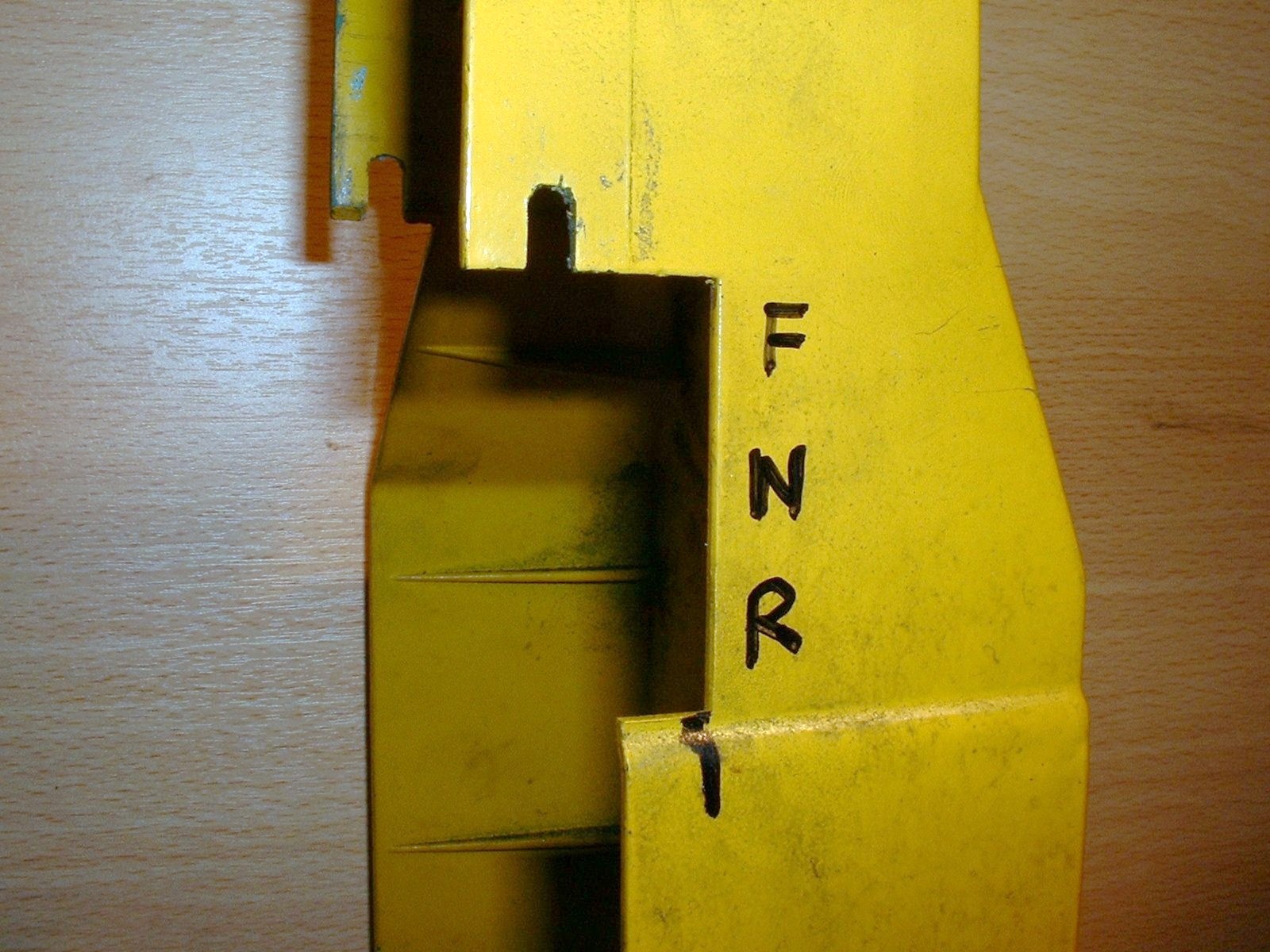
Remove the guard retaining screws and identify and mark locations for two fixing lugs. These should be just above the bottom of the vertical sides of the reverse gear mounting plate. Carefully drill the guard tapping size for M4. Replace the guard and, using a hand drill, spot through to the reversing gear mounting plate. Remove the gear plate then drill and tap an M4 hole on each side of the plate at the spotted marks. Fit two round headed screws (they do have a use!) in place, using retainer and leaving them 2mm from ‘home’.
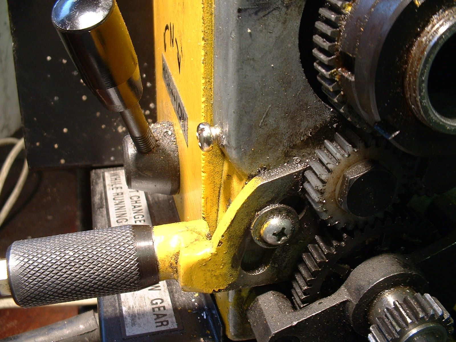
Now open the holes in the cover up to 4mm and with a razor saw or junior hacksaw, extend them into vertical slots, a shown in the photo. The letters stand for Forward, Neutral and Reverse with the tumbler gear lever.It now takes only a moment to remove the cover, with an up and out motion. Even with the largest changewheels fitted, there is no interference, and the guard is quite secure in normal use. An added bonus is that one of the existing mounting holes in the guard can be used to run a speed sensor cable into the guard, far from swarf and without any risk of fouling the gears.
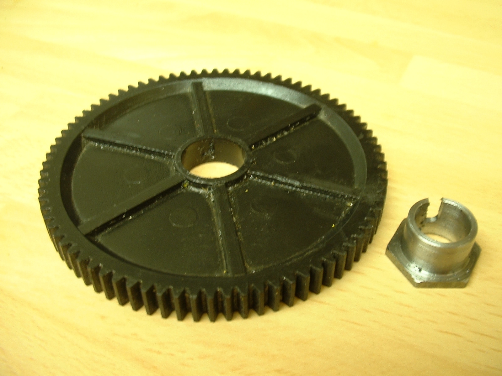
While on the subject of mini-lathe change gears, it is unfortunately possible to strip the keyway if the leadscrew is jammed. This happened to me. I found I was able to save the day by boring out the gear oversize and fitting a ‘top hat’ steel sleeve from standard hex stock, slotted for the keyway. Without the flange, the sleeve would have been too flimsy, unless made so thick that the hub of the gear would have been weakened. I used two-pack epoxy to fix the sleeve in place, and the gear continues to give good service.
- Details
- Category: Uncategorised
Welcome to Stubmandrel.co.uk
These terms and conditions outline the rules and regulations for the use of NW Environmental Limited's Website www.stubmandrel.co.uk.
NW Environmental Limited is located at: Lichfield Road Branston,Staffordshire - DE14 3HD, UK
By accessing this website we assume you accept these terms and conditions in full. Do not continue to use NW Environmental Limited's websiteif you do not accept all of the terms and conditions stated on this page.The following terminology applies to these Terms and Conditions, Privacy Statement and Disclaimer Notice
and any or all Agreements: “Client”, “You” and “Your” refers to you, the person accessing this website
and accepting the Company’s terms and conditions. “The Company”, “Ourselves”, “We”, “Our” and “Us”, refers
to our Company. “Party”, “Parties”, or “Us”, refers to both the Client and ourselves, or either the Client
or ourselves. All terms refer to the offer, acceptance and consideration of payment necessary to undertake
the process of our assistance to the Client in the most appropriate manner, whether by formal meetings
of a fixed duration, or any other means, for the express purpose of meeting the Client’s needs in respect
of provision of the Company’s stated services/products, in accordance with and subject to, prevailing law
of UK. Any use of the above terminology or other words in the singular, plural,
capitalisation and/or he/she or they, are taken as interchangeable and therefore as referring to same.
Cookies
We employ the use of cookies. By using NW Environmental Limited's website you consent to the use of cookies
in accordance with NW Environmental Limited’s privacy policy.
Most of the modern day interactive web sites
use cookies to enable us to retrieve user details for each visit. Cookies are used in some areas of our site
to enable the functionality of this area and ease of use for those people visiting. Some of our
affiliate / advertising partners may also use cookies.
License
Unless otherwise stated, NW Environmental Limited and/or it’s licensors own the intellectual property rights for
all material on NW Environmental Limited. All intellectual property rights are reserved. You may view and/or print
pages from http://www.stubmandrel.co.uk/ for your own personal use subject to restrictions set in these terms and conditions.
You must not:
- Republish material from http://www.stubmandrel.co.uk/
- Sell, rent or sub-license material from http://www.stubmandrel.co.uk/
- Reproduce, duplicate or copy material from http://www.stubmandrel.co.uk/
- Redistribute content from NW Environmental Limited (unless content is specifically made for redistribution).
User Comments
This Agreement shall begin on the date hereof.
Certain parts of this website offer the opportunity for users to post and exchange opinions, information,
material and data ('Comments') in areas of the website. NW Environmental Limited does not screen, edit, publish or review Comments prior to their appearance on the website and Comments do not reflect the views or opinions ofNW Environmental Limited, its agents or affiliates. Comments reflect the view and opinion of the person who posts such view or opinion. To the extent permitted by applicable laws NW Environmental Limited shall not be responsible or liable for the Comments or for any loss cost, liability, damages or expenses caused and or suffered as a result of any use of and/or posting of and/or appearance of the Comments on this website.
NW Environmental Limitedreserves the right to monitor all Comments and to remove any Comments which it considers in its absolute discretion to be inappropriate, offensive or otherwise in breach of these Terms and Conditions.
You warrant and represent that:
- You are entitled to post the Comments on our website and have all necessary licenses and consents to do so;
- The Comments do not infringe any intellectual property right, including without limitation copyright, patent or trademark, or other proprietary right of any third party;
- The Comments do not contain any defamatory, libelous, offensive, indecent or otherwise unlawful material
or material which is an invasion of privacy - The Comments will not be used to solicit or promote business or custom or present commercial activities
or unlawful activity.
You hereby grant to NW Environmental Limited a non-exclusive royalty-free license to use, reproduce,
edit and authorize others to use, reproduce and edit any of your Comments in any and all forms, formats
or media.
Iframes
Without prior approval and express written permission, you may not create frames around our Web pages or
use other techniques that alter in any way the visual presentation or appearance of our Web site.
Reservation of Rights
We reserve the right at any time and in its sole discretion to request that you remove all links or any particular
link to our Web site. You agree to immediately remove all links to our Web site upon such request. We also
reserve the right to amend these terms and conditions and its linking policy at any time. By continuing
to link to our Web site, you agree to be bound to and abide by these linking terms and conditions.
Removal of links from our website
If you find any link on our Web site or any linked web site objectionable for any reason, you may contact
us about this. We will consider requests to remove links but will have no obligation to do so or to respond
directly to you.
Whilst we endeavour to ensure that the information on this website is correct, we do not warrant its completeness
or accuracy; nor do we commit to ensuring that the website remains available or that the material on the
website is kept up to date.
Content Liability
We shall have no responsibility or liability for any content appearing on your Web site. You agree to indemnify
and defend us against all claims arising out of or based upon your Website. No link(s) may appear on any
page on your Web site or within any context containing content or materials that may be interpreted as
libelous, obscene or criminal, or which infringes, otherwise violates, or advocates the infringement or
other violation of, any third party rights.
Disclaimer
To the maximum extent permitted by applicable law, we exclude all representations, warranties and conditions relating to our website and the use of this website (including, without limitation, any warranties implied by law in respect of satisfactory quality, fitness for purpose and/or the use of reasonable care and skill). Nothing in this disclaimer will:
- limit or exclude our or your liability for death or personal injury resulting from negligence;
- limit or exclude our or your liability for fraud or fraudulent misrepresentation;
- limit any of our or your liabilities in any way that is not permitted under applicable law; or
- exclude any of our or your liabilities that may not be excluded under applicable law.
The limitations and exclusions of liability set out in this Section and elsewhere in this disclaimer: (a)
are subject to the preceding paragraph; and (b) govern all liabilities arising under the disclaimer or
in relation to the subject matter of this disclaimer, including liabilities arising in contract, in tort
(including negligence) and for breach of statutory duty.
To the extent that the website and the information and services on the website are provided free of charge,
we will not be liable for any loss or damage of any nature.
- Details
- Category: Uncategorised
You can buy my books including the Mini-Lathe, Norden: Building a Victoirian Steam Engine and The Home Workshop Dictionary using the links below.
I just bought your book (The Mini Lathe), and have to say how great it is! I have the usual, L H Sparey, ME Lathe Manual, Dave Fenner (Workshop Practice) Stan Bray, but this is far better. Specific, targeted, carefully explained, good photos & drawings, just the job! - Geoff
NOW! Most books available as either Hardback/Paperback or for Kindle
- Details
- Category: Uncategorised
Page 2 of 2