If you find this website useful, please check out my books or visit my Amazon Author page. Or even Buy Me a Coffee!
Model Engineering
Model Engineering
Ever since I was a boy, I was in awe of the working mechanical models to be seen in the pages of Model Engineer magazine or on television programmes like Bob Symes' Model World. In 1999 I managed to acquire both a daughter and a lathe, and against all the odds started my journey in model engineering.
You can buy my books including the Mini-Lathe, Norden: Building a Victoirian Steam Engine and The Home Workshop Dictionary using the links below:
Hardback and Paperback Books
Ebooks and Kindle
Percivalk Marshall was a remarkable man, the founder of Model Engineer Magazine and the Society of Model and Experimental Engineers, both in 1898. He went on to edit the magazine through two world wars as well as publsihing many otehr books and magazines written by himself and others.
In the 1930s Percival Marshall recorded a gramophone message across two sides of a 78rpm disc, introducing model engineering.
Below you can see a video of various model engineering activities to accompany his message.
Download the recording (audio only): Percival_Marshall_Speaks.mp3
- Details
- Category: Model Engineering
When you are making heavily loaded parts like crankshafts, gears, pistons or pivots you are likely to turn to one of the high carbon steels. These are generally more expensive than mild steels and more difficult to machine to a high finish, so you will only choose them when their special properties are needed.. Let's look at the commonest examples: EN16, EN19 and EN24. Their high carbon content allows them to be hardened through heat treatment, and the can be supplied in as-produced condition or in the T (heat treated) condition which has less stress and better machineability.
EN16
EN16 is also known by the European designation 605M36. It is a strong steel that is a step up from EN8 (see mild steels) in terms of its ability to withstand wear and shear loads. In smaller sizes it is usually supplied in the 'T' condition (heat treated) as EN16T which maximises its shock resistance and helps machineability.
Although it is stronger than EN8, it still has a certain degree of give which makes it a good choice for load bearing and stressed parts such as connecting rods. It is not too demanding to machine but you do need to use cutting fluid.
EN19
EN19 or 709M40 is a really strong steel ideal for gears and other highly stressed components. It is quite tough to machine and the use of carbide tooling is recommended but not essential. Use plenty of cutting fluid, especially with HSS. Unlike EN16 it is easy to polish to a good finish.
EN 19 is also available in heat treated (EN19T) condition. One specialist product are accurately drawn hard-chromium plated bars which can be useful for things like guide bars.
EN24T
EN24T, which is also listed as 817M40, is a very strong steel that is usually supplied in the 'T' condition. It is very wear resistant but this can be increased even further by induction hardening or nitriding. It can be hardened in the workshop by heating followed by oil quenching, but it should be tempered at a relatively high temperature to prevent brittleness. For this reasons sharp edges and corners should be avoided - it has less resistance to shock loads than EN16 and EN19.
It is a demanding metal to machine, but with carbide tools and high surface speeds you can achieve a very good finish straight from the tool.
See Mild Steels for more general purpose steels.
- Details
- Category: Model Engineering
Mild steel is not a specific material, but rather a catch-all for steels (iron alloys) that have relatively low-levels of carbon. This means that generally they can't easily be hardened (unlike high-carbon steels) and they are relatively ductile (easy to bend). While this limits their applications, it does make them relatively easy to produce and they are especially suited to to 'drawing' or 'cold rolling' into sized bars and flats. They are also generally easy to machine.
Though mild steels have a low carbon content, they are still classed as 'carbon steels'. The 'mild steels' most commonly encountered in the UK are designated EN1a, EN3 and EN8.
EN1a
Also known by the instantly forgettable code of 230M07, you are still more likely to find 'bright mild steel' classified as EN1a. EN1a is available as round, square and flat bar with a good finish and fairly accurately sized (you can buy accurate ground bars as well). It is a great all-round material for parts that are not going to be highly stressed or subjects to high levels of wear. It might not be the ideal material for making machine tools for use in a factory, but is usually fine for making your own devices. It machines easily and gives a good finish, the variant EN1a Pb has added lead and is even freer machining.
It's low carbon content makes it virtually impossible to harden but it can be case hardened (although EN1a Pb doesn't case harden well). It should not be welded.
Bright drawn metal has a lot of 'locked in' stress. If you do any asymmetrical machining of EN1a bar don't be surprised to see it bend like a banana! This, rather than its relatively low strength, makes it unsuitable for parts such as crankshafts.
In practice, you are likely to find that EN1a is the most useful general purpose, inexpensive material for non-critical components but is best avoided for bolts, studs or high wear/load parts.
EN3
EN3, also known as 070M20, is a slightly higher carbon content mild steel that is suitable for welding and one of its main uses is for making steel fabrications. It has good machineability, but isn't quite as pleasant to work as EN1a, being best machined with a lubricant.
It is typically available as bright drawn bars and a hot rolled bars. Hot rolled steel is less accurately sized and has a poor finish but it is stress-relieved so it is the ideal alternative to bright bar for asymmetrical or heavily machined parts. It is also suitable for making lightly loaded fixings.
EN3 can be case hardened.
EN8
EN8, or 080M40, is actually a medium-carbon steel but it is usually classed as a 'mild steel'. It is stronger than EN3 but does not machine so well and a cutting fluid of some sort is essential to get a reasonable finish.It is generally available a bright drawn round bars.
Like EN1a and EN3 it tends to bend rather than break, which can be a useful property in situations where complete failure would cause a hazard. Unlike EN3 and EN1a it is reasonably easy to harden EN8 to increase its surface hardness and wear resistance, but it does not become as hard as high-carbon steels.
EN8 welds well and even fairly thick sections (up to 18mm) can be welded without preheating. It is a good choice for parts or fixings that have to bear moderate loads where going to a higher carbon steel would be overkill.
For applications where you do need extra strength see High Carbon Steels
- Details
- Category: Model Engineering
If you model historic machines they will almost always have plain bearings. Plain bearings can also be the best solution for other purposes having performances equal to ball races whenever adequate lubrication is provided.
Although you will often read references to bearing 'brasses', the most common metals used for plain bearings are actually bronzes. Brasses are alloys largely of copper and zinc, and though they will serve as bearing materials for lightly loaded models the bronzes (which are alloys of copper with tin and other elements) are generally much harder wearing.
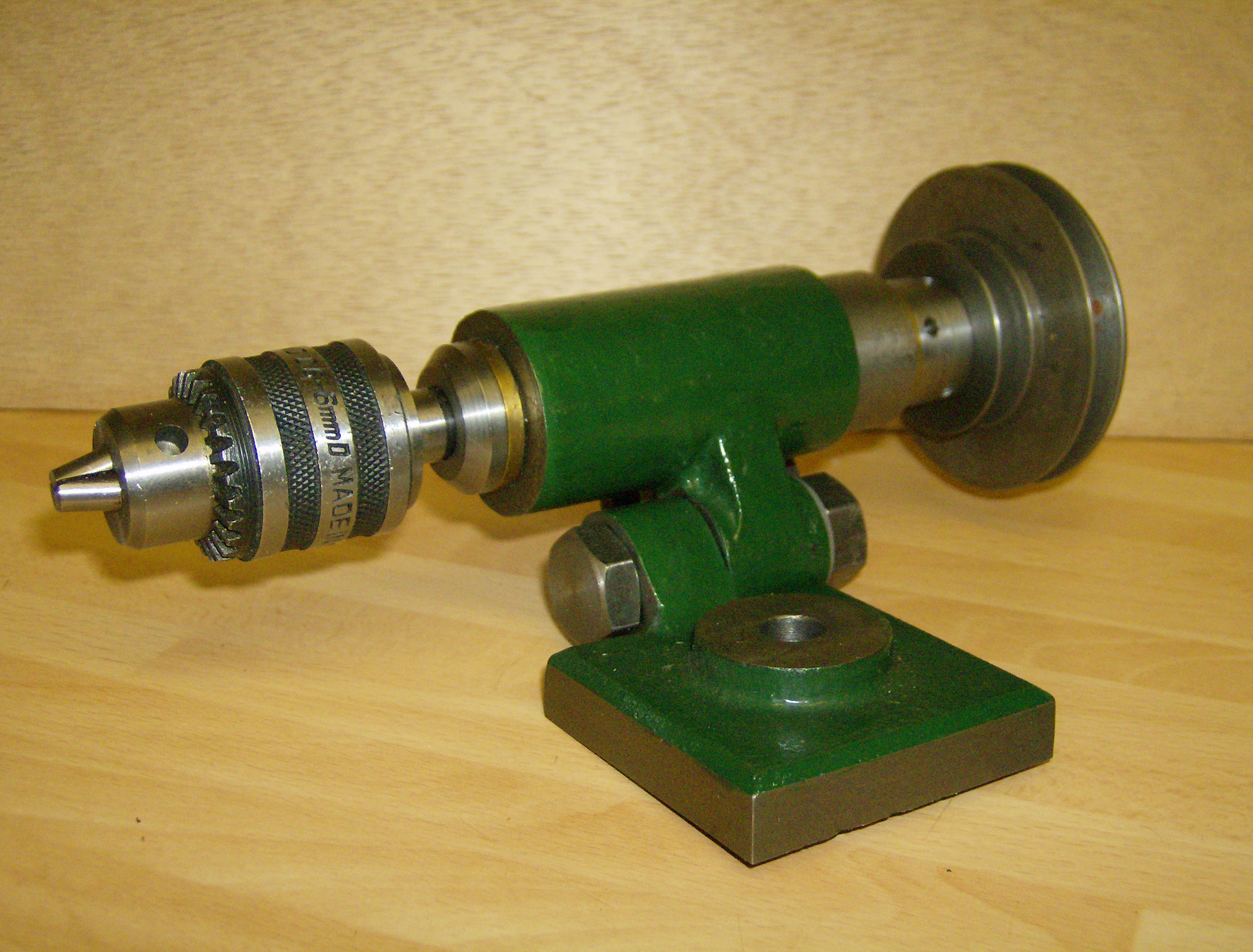
A Potts Milling Spindle with plain bronze bearings
Let's look at two bronzes which meet most of the needs of hobbyists. They both have a similar dark, reddish colour and often bear a dark spiral pattern and feel very heavy.
PB1
Most hobbyists will instinctively turn to 'phosphor bronze' - usually supplied as PB1 a very tough, hard and hard-wearing material that is ideal for heavily loaded bearings.
The downside of PB1 is that it is not a particularly pleasant metal to machine. It can produce tough, raggedy swarf but the worst problem is that it tends to 'close up' when drilled. This nasty habit can cause drills or reamers to jam and even break giving phosphor bronze a reputation for difficultly in machining.Some people even go as far as grinding drills with off-centre tips so they drill over-size to avoid these problems.
Rather than spoiling your best drills, is there an easily available alternative?
SAE 660 Bronze
Fortunately there is! SAE 660 is a bronze with a high lead content that both makes it a lot easier to machine and also helps it bearing properties. You can pretty much treat it like a free-cutting mild steel. It's not as good for extreme load bearing or very high speeds as PB1 but for 9 out of 10 (or more) hobby applications you are better off using SAE 660.
The good news is that SAE 660 is often rather cheaper than PB1, sometimes around 3/4 of the price, and is readily available from most metal stockholders.
As well as being available as drawn or continuously cast bars they are both available in tube form. This doesn't just save you some machining work, work the reduced weight of buying tube can save you a significant amount when buying what is one of the more expensive metals. Fortunately, we often find we only need a short end of material for bearing use and many specialist hobby suppliers will sell very short lengths.
'Oilite' Bushes
It's worth mentioning 'Oilite' bushes, and other similar bushes. These are made from sintered bronze and impregnated with oil to provide plain bearings that need minimal maintenance. Usually these should be bought in the size you need and may well prove to be a cost effective alternative to making your own bearings..
Bear in mind that the housing size should be carefully made to the right size for the bearing as if it is too tight the bearing will close up. You may often read that such bushes should never be machined, in practice they can be finish machined but a very sharp tool should be used to avoid 'closing up' the micro-pores in the material.
See also:
- Details
- Category: Model Engineering
Universal Thread Cutting on a Mini Lathe
Sooner or later, all model engineers need to cut threads on their lathe. Either the thread is simply too large for a tap or die, it is an awkward size, or a degree of accuracy is required that cannot be achieved by other methods in the home workshop.
On lathes screwcutting is typically achieved by gearing the mandrel to the leadscrew. If the gearing is 1:1, the thread cut will be the same pitch as the leadscrew (though not necessarily the same form or diameter). By varying the ratio of the gears, via a gearbox or using a set of change gears, screws of various pitches can be cut easily and accurately. This method of screw production was devised by Henry Maudsley around 200 years ago. Following Sir Joseph Whitworth’s standardisation of screw threads, this technique for screwcutting played a critical part in the advent of mass production in the nineteenth century.
If we need to produce threads that will only mesh with others we have made, standardisation is not an issue, and we can use any convenient pitch for the work in hand. In many cases, however, we will want to use bought in fixings or mate parts with threads cut using standard taps or dies. In these case we need to cut threads to standard sizes.
The ‘mini-lathes’ available from several UK sources are generally available in either ‘metric’ or ‘imperial’ leadscrew versions. The supplied changewheels allow the cutting of most of the usually encountered metric series threads with a 2mm pitch leadscrew. Similarly, imperial sizes are easily cut with the 16tpi leadscrew. In each case the various sizes are simple ratios to the leadscrew, and the required changewheels are given on tables on the machine and in the manual.
What if we want to cut metric threads on an imperial machine, or vice versa? One can change over the leadscrew, but this takes time, as the apron must be removed and the clasp nuts replaced and adjusted as well. Is there an easier way?
One inch equals precisely 25.4 millimetres – though in the not too distant past the conversion wasn’t quite so neat! If we introduce a 254-tooth changewheel into our set-up, we can now convert precisely between the two systems. There is a problem though, a 1-module 254-tooth gear is 254mm in diameter! A 127 tooth gear could be used, as it is exactly half of 254, but it would still be about 5” across. You could accommodate such a gear by making a new mounting banjo, but you might also need to add further idler gears. The whole set-up would be rather clumsy.
The answer is a 63-tooth gear. It may seem that 63 is ‘close enough’ to half of 127 to do the job, but it isn’t – it would produce errors of around 2%, acceptable for some purposes, but not for many others. The 63 tooth gear arises from another, fortuitous bit of maths.
1mm pitch is 25.4 threads per inch. To cut 25.4 tpi on a 16 tpi leadscrew we need a ratio of 16:25.4, this works out at 0.62992:1, or almost exactly 63:100. If we introduce the ratio 63:100 into our gear train then a 16tpi leadscrew will cut a 1mm pitch thread – actually 1.00125mm pitch – well within the tolerance of any other aspect of the process. To translate this into standard change wheels we can use:
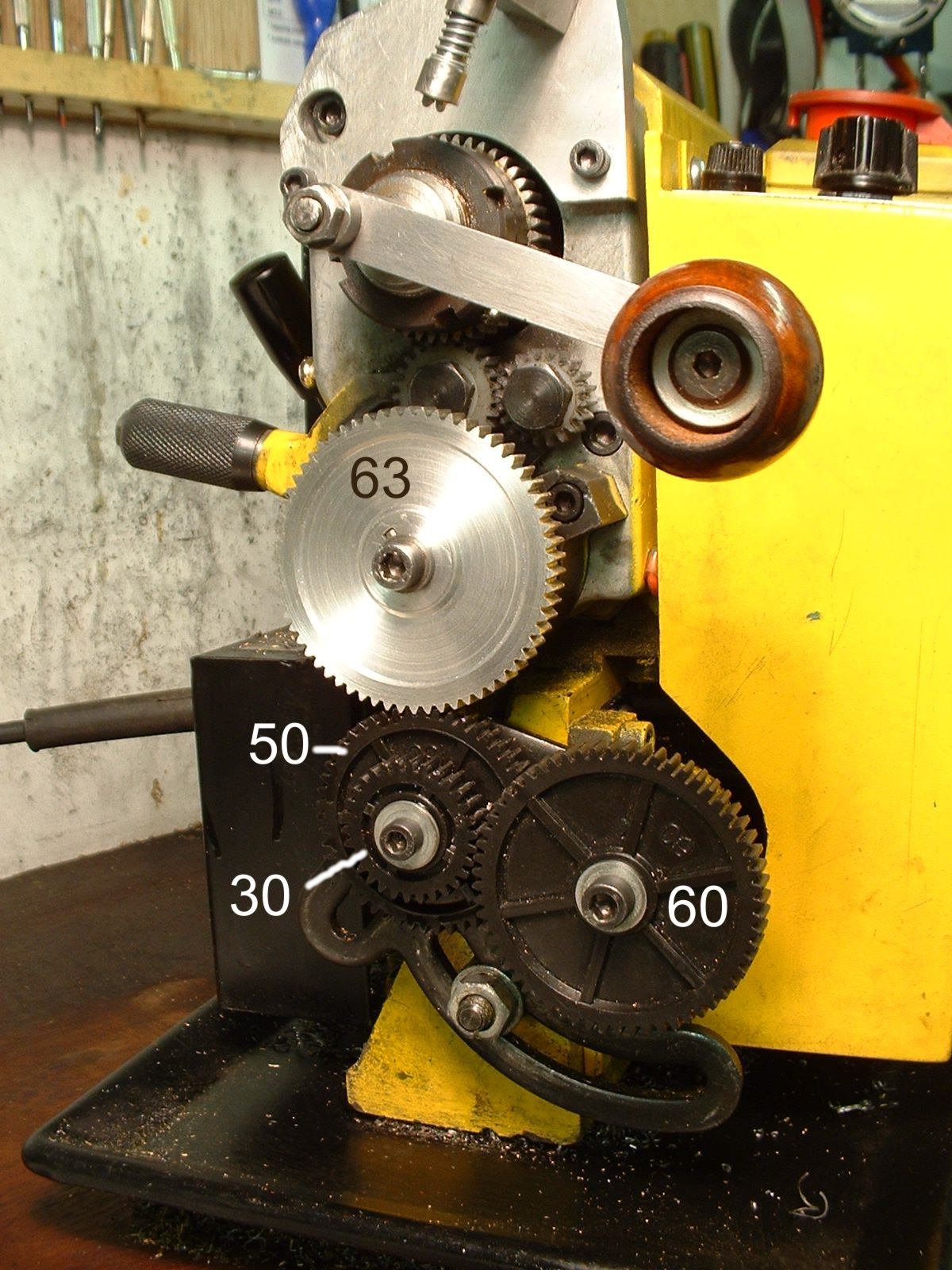
63/100 = 63/50 *1/2=63/50 x 30/60
This means a 63-tooth gear on the fixed stud, driving a 50T joined to a 30T on the intermediate pair, and finally a 60T on the leadscrew itself.
Conversely, a ratio of 100:63 allows a 1mm metric leadscrew to cut a 16tpi thread with the same accuracy. In fact, the standard metric leadscrew for mini lathes has a pitch of 1.5mm, so the 100:63 ratio would therefore cut 16 x 1.5 = 24 tpi, but this is dealt with by putting the ratios 2/3 and 100:63 in series. To get standard changewheels:
100/63 x 2/3 = 50/63 x 4/3 = 50/63 x 4/3 = 50/63 x 40/30
Just for clarity, this is a 50-tooth gear on the fixed stud, driving the 63T joined to a 40T on the intermediate pair, and finally a 30T on the leadscrew itself.
From these basic ratios, it is possible to derive a ratio for any other metric or imperial thread. Armed with a 63-tooth wheel and the right changewheel ratios you can cut almost any standard metric or imperial thread.
Aided by a spreadsheet, I have produced tables showing suggested combinations of changewheels for the three common thread families for both metric and imperial leadscrews. For the sake of my own sanity I have excluded many ‘round’ pitches which are achievable, but instead focused on ‘standard’ threads. The tables only use the changewheels supplied with the lathe plus the 63-tooth gear. Owners of metric lathes may find they do not have as great a selection of change gears, limiting the range of threads that can be cut. It is possible to obtain the gears as spares, or even to purchase a full ‘imperial’ set of metal gears.
Mini Lathe Change Wheel Tables
Because of the limitations in the change gears available, not all conversions can be absolutely precise, especially for the BA series. There are also a few issues with ‘odd’ imperial sizes and the smallest metric threads. Even so, in the worst cases the ratios given should still allow you to cut threads that will mate with standard threads. In a few cases better results could be achieved by doubling up gears not duplicated in the standard gear set.
The metric tables cover every preferred value from 0.2 up to 6mm pitch. The 63-tooth gear allows the imperial machine to produce every thread, with no error greater than 0.8%. The imperial table covers all standard BSW, BSF, BSP, UNF, UNC and Model Engineer pitches. With the 63-tooth gear the metric machine can produce all these threads up to 4TPI to better than 0.1%, and up to 2.5TPI to less than 1% error. The 63-tooth gear allows the otherwise elusive 3.25 TPI to be achieved on the imperial machine. The 63 tooth gear also allows both metric and imperial machines to produce all British Association threads from 0BA to 16BA, accurate to better than 1%.
Do not attempt to screwcut threads coarser than about 8 tpi directly – the load on the gears with the leadscrew geared up this much is inviting disaster. Such threads can be produced by thread milling, driving the mandrel by turning the leadscrew. You will need, however, to make the simple modification of fitting a leadscrew handle.
All you need now is a 63-tooth changewheel, 1-module, 20º pressure-angle, 5/16” thick and bored 12mm with a 1/8” keyway. I will explain how you can make such a gear. If you would prefer to buy a suitable gear, 63-teeth is not a standard production number and they are normally expensive and would also need to be adapted to fit the lathe. Fortunately, Arc Euro Trade are planning to have a batch of suitable gears made up ready to fit to mini-lathes.
I made my gear in a few hours, but had the advantage of a milling machine and rotary table. It is possible to make the gear on a mini lathe alone, but if so you will need some form of cross-slide dividing attachment and a little ingenuity.
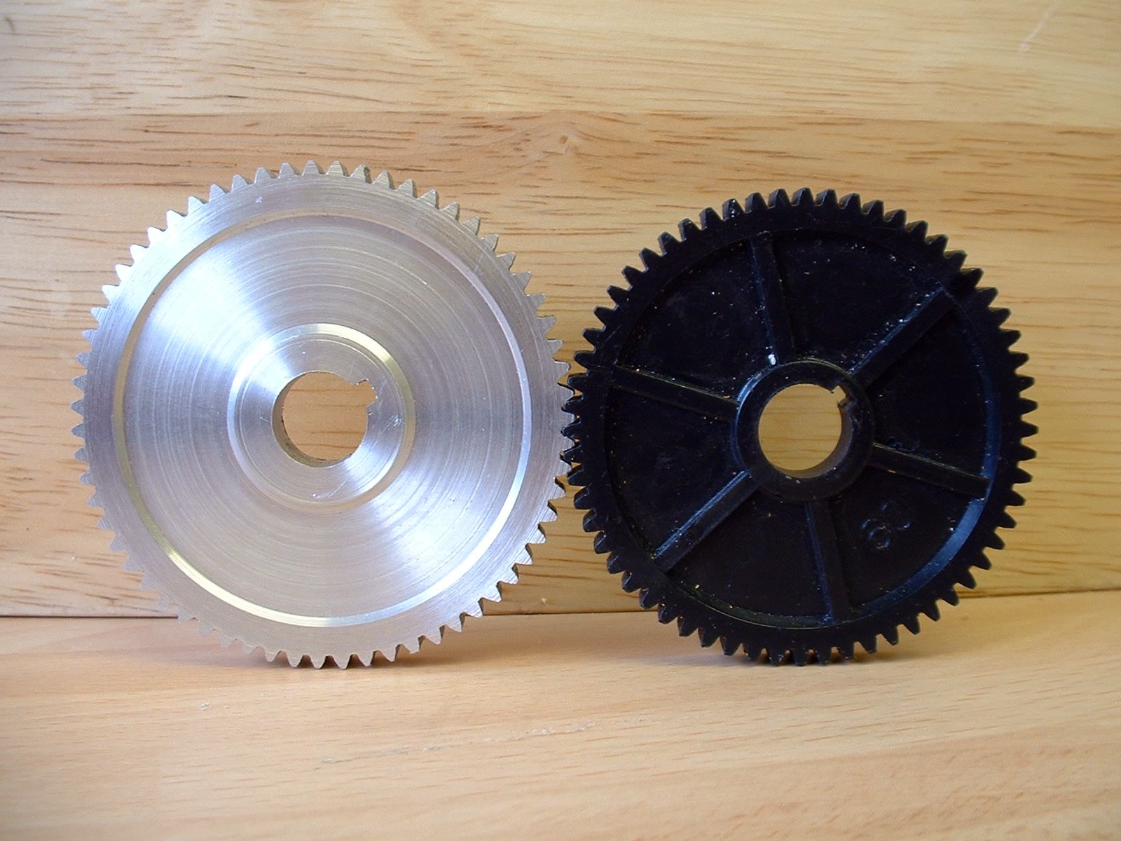
The supplied change gears are made of plastic (nylon or acetal), except the 20-tooth gears, which are steel. I decided to make a gear of aluminium alloy, partly because I had material of suitable size, but also because it would be compatible with all the existing gears. Most aluminium alloys are also easy materials to work, an advantage when using a single point form cutter. I face a blank to 8mm thick and mounted it in the four-jaw chuck, bored an accurate 12mm hole in the middle and relieved the face slightly for appearance sake. I then mounted the blank on a stub mandrel. This was turned from a short section of hex bar, held in the 3-jaw chuck. I then drilled and tapped the end of the stub M6 using the tip of a taper tap. Finally I slit the stub and cleaned up the edges of the slot. With the blank on the mandrel, and a suitable screw screwed home tight, it opened it up just enough to hold the blank securely. Alternatively, you could put an M8 thread on the end of the mandrel and use a nut to hold it all secure.
I mounted the blank and turned it to size at 65mm. In fact it was slightly small at 64.98 millimetres. This meant I had to reduce the cutter infeed by 0.01mm.
Now I needed a number 2, 20º pressure angle, 1-module cutter for a 63-tooth gear. Bought cutters are expensive but homemade cutters can give good results. There are many ways of making gear cutters. I have made cutters using the ‘button’ method described in Ivan Law’s Gears and Gearcutting (Workshop Practice Series No. 17), which describes all aspects of the process with detail and clarity. As I was only planning to make one gear in a fairly soft material, I decided that a complex cutter was not needed. Tubal Cain declared that the only time he made a flycutter to make a gearwheel, he filed it up using a similar size gear as a template, so I did the same. I used a 1/2” by 3/4” piece of 1/8” gauge plate and the 65-tooth changewheel as a template. I started by angling the end to provide relief, then roughed out a wedge shape with a smooth file.
A half-round needle file made hollowing the sides of the cutter easy. Gauge plate is quite tough and files slowly, so it’s easy to approach an accurate shape gradually. Once I had a good fit, I drilled the plate so that it could be fitted to a holder. My cutter holder is an MT2 arbor with two M6 holes in it – one for the fixing screw and one for a second screw as a stop.
I hardened the gauge plate by heating to red-hot then dropping it in sunflower oil. I then tempered it at 150º in a thermostatic fryer. The right temperature for mushrooms, apparently. Once cool I used a diamond slip to polish the front face of the cutter.
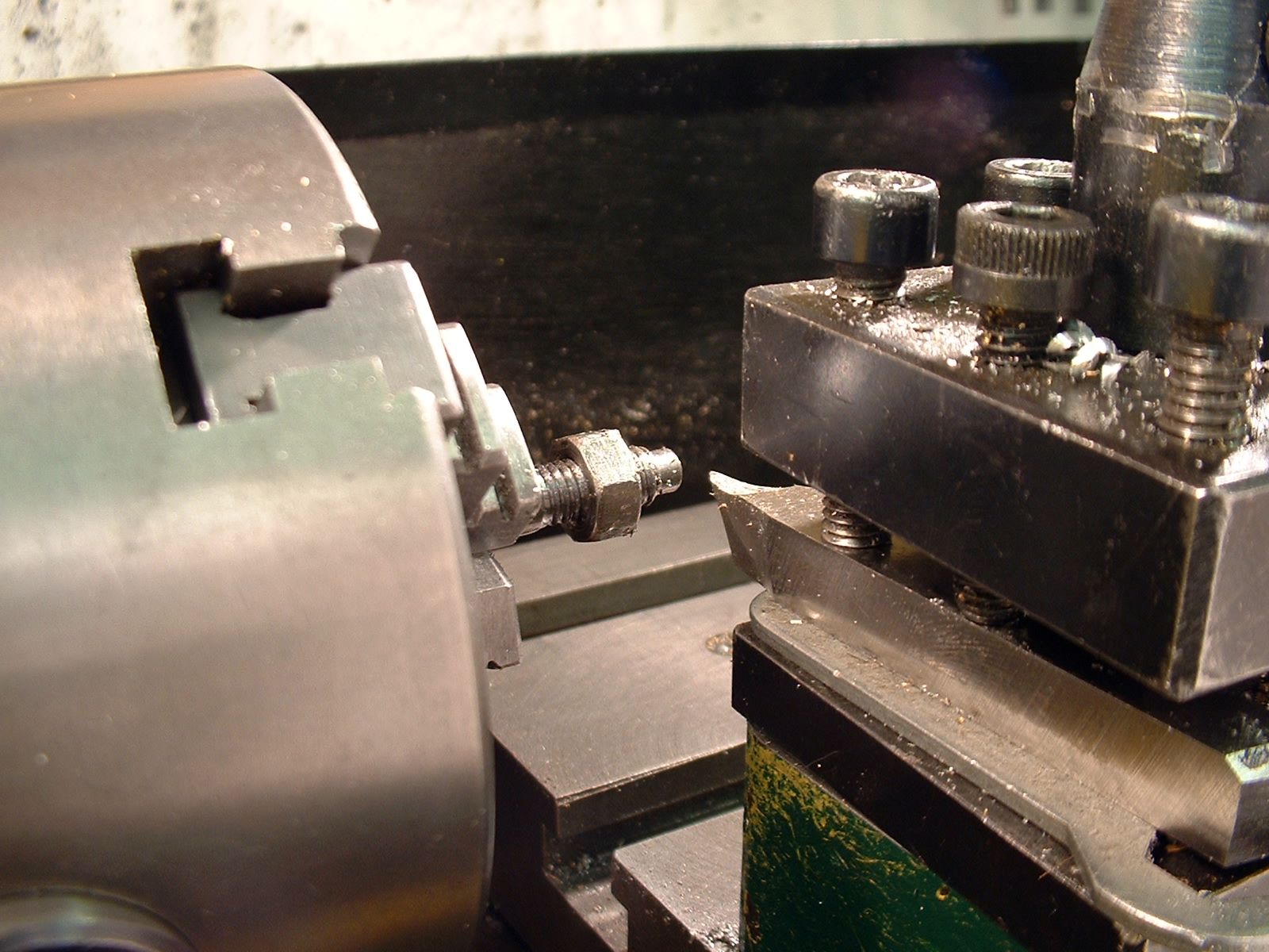
I transferred the blank, still in the three-jaw chuck, to a rotary table on my milling machine (the photo below shows a smaller pinion being cut, but the setup is the same). The critical issues for cutting any gear are getting the cutter dead on the centreline of the blank and the correct cutting depth for the cutter. As blank was undersize, I reduced the infeed appropriately. There was some ‘extrusion’ of metal at the crest of the teeth. I took a skimming cut off the crown of the teeth, but still decided to tidy up the ‘edge’ of each tooth with a needle file.
If you don’t have a suitable dividing device, you will need to make a simple spindle of some kind to support the gear and allow it to be indexed and clamped for cutting each tooth. Various designs for both simple and complex indexing and dividing heads have featured in MEW over the years. If you fit a wooden disk with a suitably marked paper scale on the other end, you can then use a simple pointer and index by hand. A 101mm diameter disk is almost perfectly sized for a paper scale with 63 divisions 5mm apart to wrap around it.
The final task was slotting the 1/8” keyway. I used a toolpost held ‘ram’ type device as described by Stan Bray (Useful Workshop Tools, Workshop Practice Series No. 34). Slotting the light alloy was a pleasure compared to using the ram on steel! To test both the gearwheel and the tables I cut an M6 test piece on my imperial machine, using a mandrel handle to turn the lathe. I’m proud to say that an M6 nut went straight on without slop or tightness. I can now, in theory, cut almost any type of thread to a good standard of accuracy. I have since cut various metric threads, including an M32 by 1.5mm pitch thread for an ER25 collet nut, using this gear.
Before finishing I must make a few caveats. Cutting very fine threads to a good form is a challenge, if not impossible. Making BA threads down to about 8BA is possible using a very sharp tool dead on centre height – noting that the thread angle for BA is 47 1/2°. With smaller threads the cutting forces tend to bend the work.
At the other extreme cutting the large pitch threads (those where the leadscrew is turning faster than the mandrel) may impose damaging strain on the gear train. These should be cut by thread milling, using the leadscrew to turn the mandrel with the lathe switched off. To do this a toolpost milling spindle and a leadscrew handwheel such as that described by Alastair Sinclair (Model Engineer’s Workshop, issue 91, July 2003) will be needed.
You should also bear in mind that you will not be able to use the leadscrew dial indicator when cutting non-standard threads. There are other ways, but the simplest and most reliable (if tedious) technique is to keep the clasp nuts engaged, and wind the cutter back between each cut. Again, a leadscrew handwheel is essential.
Mini Lathe Change Wheel Tables
Users of other lathes may find these tables useful. The 2mm pitch tables will suit some of the slightly larger metric lathes. The ML7, Super 7 and many other older British lathes have 8TPI leadscrews, so the imperial tables can be used with simple modifications. By doubling the teeth on an input gear or halving the teeth on an output gear to increase the overall ratio by 2:1 same threads can be cut. Alternatively, simply select the set-up for the thread with half the pitch of the one you require, for example the 0.5mm pitch set-up will give 1mm on a Myford.
There are nearly 33,000 theoretical combinations of the standard mini-lathe changewheels, though many are trivial duplications or impossible to set up. I am sure there are still a few improvements to be made to the tables, and though the formulae used ought to have eliminated significant errors, some of the ratios may prove hard to set up due to overlapping gears. I would be pleased to hear from any reader who discovers any improvements or errors.
For more adventures in thread cutting check out Brian Wood's book, or my own book The Mini Lathe:
- Details
- Category: Model Engineering
Page 1 of 3
- You are here:
-
Home

- Model Engineering