If you find this website useful, please check out my books or visit my Amazon Author page. Or even Buy Me a Coffee!
Workshop
In a Model Engineer's Workshop
I had my first workshop at about the age of fourteen. It was only a draughty, unheated Victorian conservatory, five feet square with a crude bench, but it was my space to make models, electronics and generally star accumulating bits and pieces. It seemed natural enough, after all my father and grandfather both had workshops. Sadly when I went to college at 18, I had to make do with tables and odd corners for about fifteen years, but eventually I got a proper workshop again.
This section of the website will gradually accumulate some of the tools and techniques I've got to grips with over the years. Some of these may have previously appeared in print in a slightly different form.
Making Workshop Tools
The Right Temperature for Hardening Silver Steel
Making a Micro Adjustable Surface Gauge
Accessories and Machines
E. Bourdon's Patent Compound Gauge
Workshop Data
Workshop Ramblings
Are BA Fixings Metric or Imperial?
See all articles tagged WORKSHOP
Making the QCTP Block
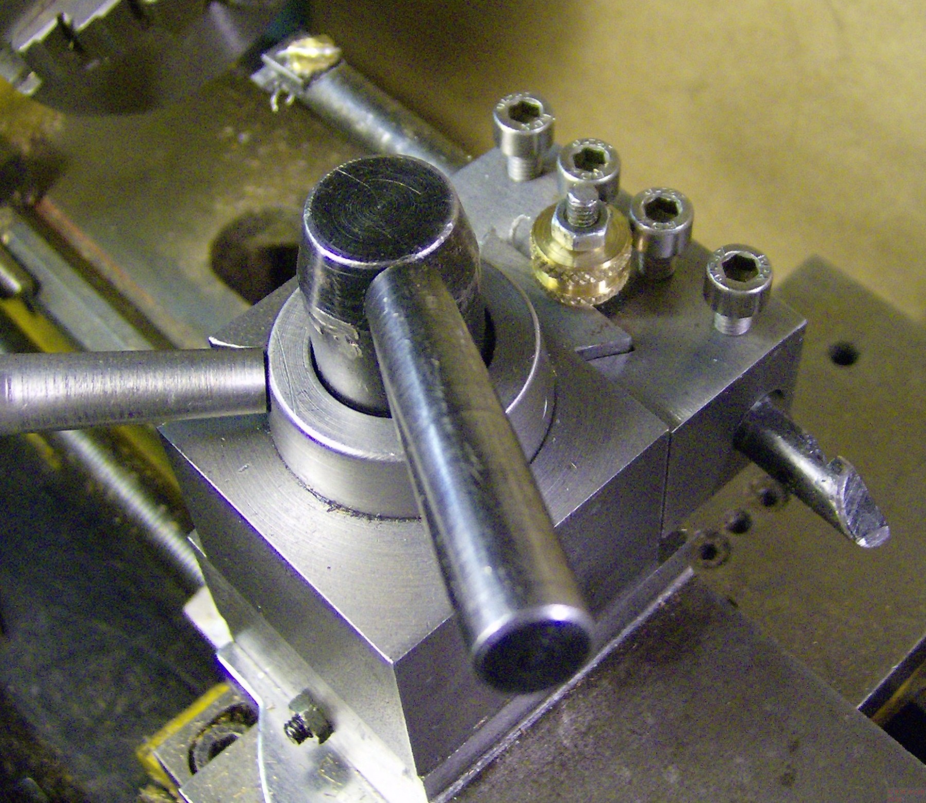
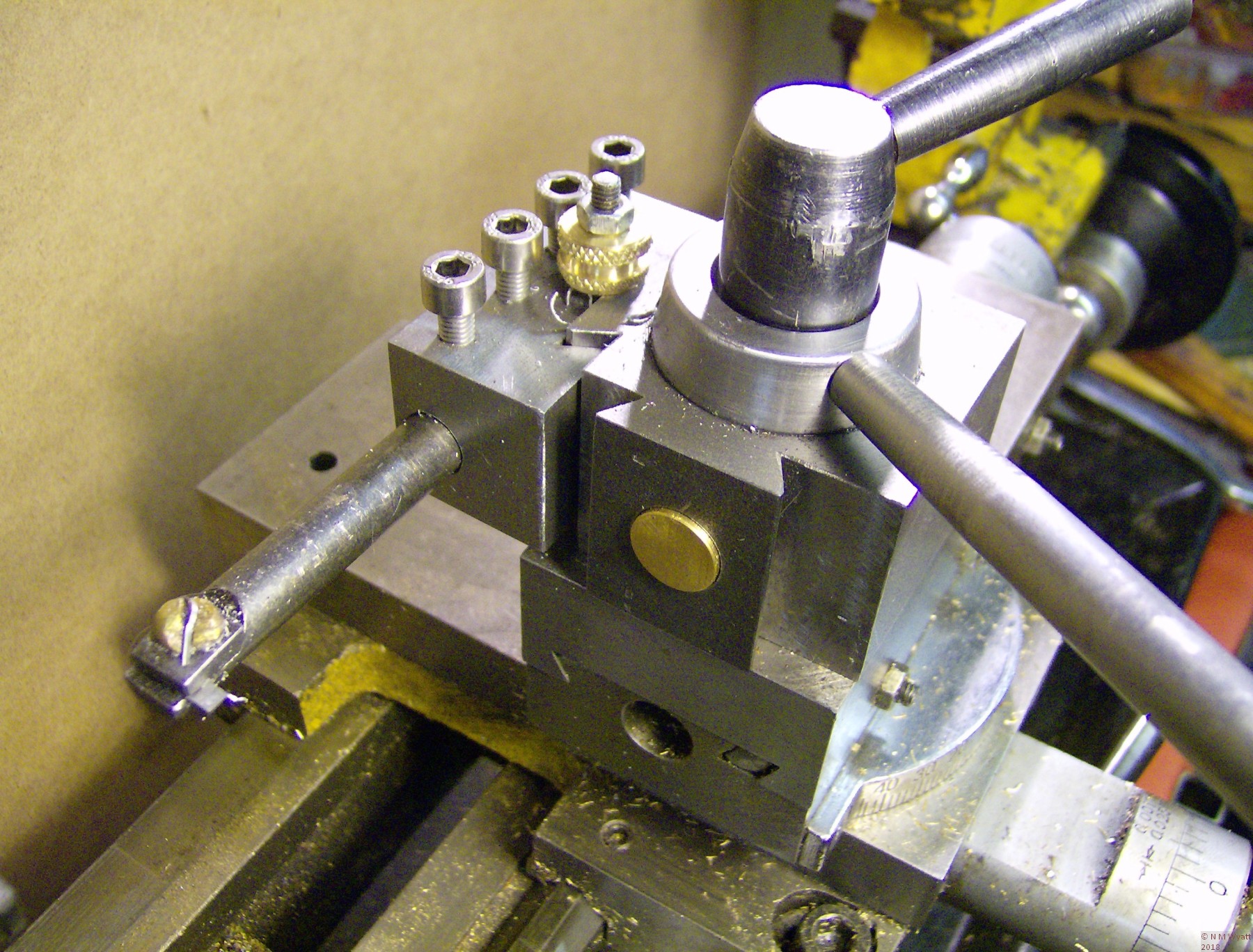
This article show you how to make this Quick Change Toolpost which suits popular 7x12 and similar mini-lathes
The design is also suitable for almost any lathe of about 3 1/2" or 80mm centre height including Myford ML7 and Super 7 lathes.
You can download a free set of plans for the QCTP design with this link.
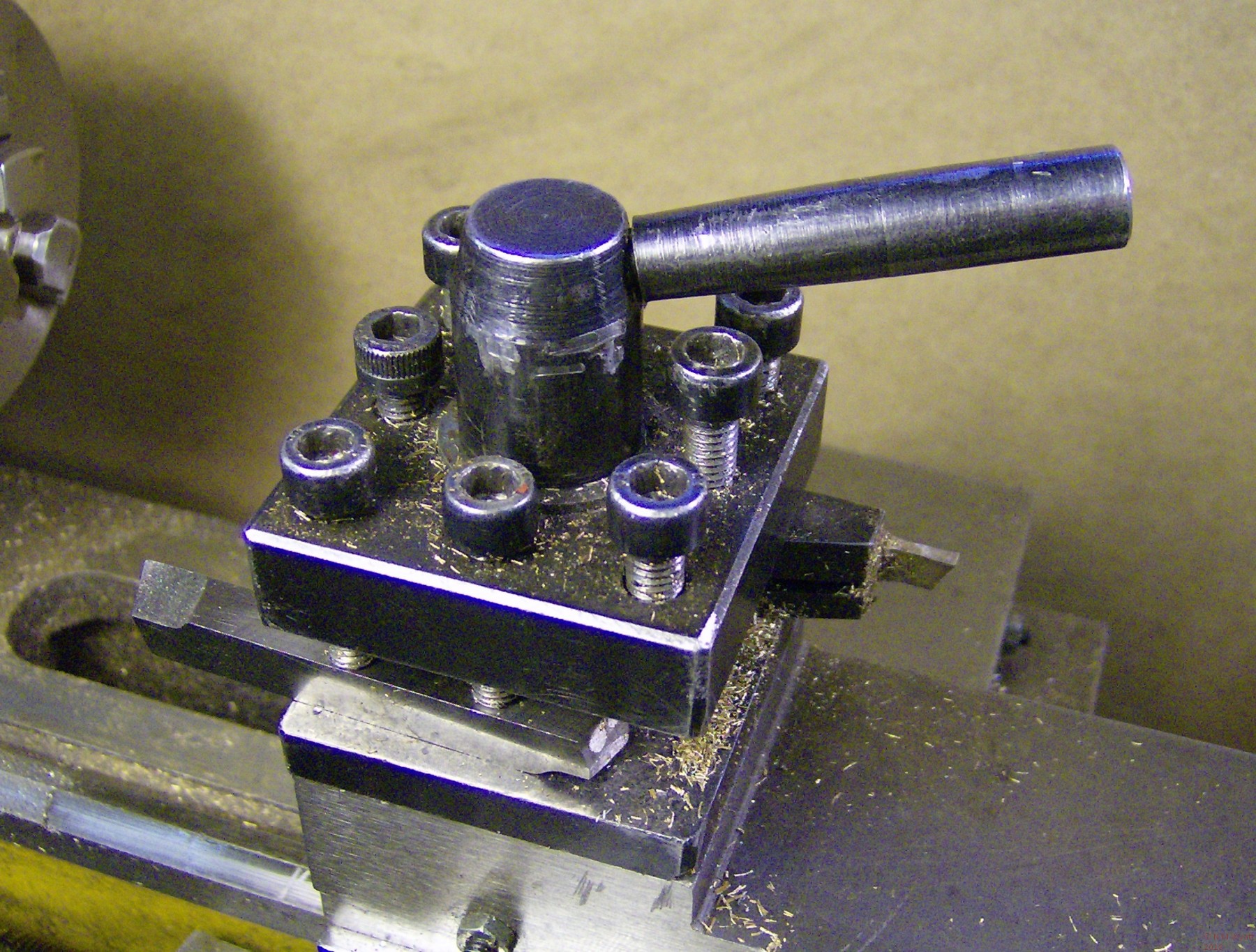
Whenever you tackle a complex turning task, one that involves repeating a series of operations on several parts, you may get frustrated by the limitations of the standard 4-position toolholder.
Four Position Toolholder
One problem is that, in practice, these normally only holds two tools conveniently. One solution is a Quick Change Tool Post, a variety of suitable ‘QCTP’s can be bought for mini lathes, but once you factor in the need for a good set of compatible toolholders (I have twelve, and could usefully have twice as many) the cost starts to spiral. An alternative is to make one yourself, and although this is not a raw beginner’s project, it is a good test of your skills once you are more familiar with the lathe. Note that although it can be made entirely using the lathe itself, milling the dovetails and tool holder slots is much easier if you have access to a milling machine. This is also a project which is made much easier if you have a metal cutting power saw of some kind. There is a lot of quite large section mild steel that needs cutting, and if you have to do this by hand, be prepared for some hard work.
The design is based on the Nakamura Toolpost, but this has a couple of limitations – the piston does not retract automatically and has to be pushed back; it only takes one toolholder; and it overhangs the topslide excessively. The changes here to address the last two of these issues by adding a second dovetail and piston and reducing the overall dimensions of the block. Internal springs cause the pistons to be self-retracting. The toolholder offers ease of use and rigidity, the handle requiring very little pressure to fully lock the holders. Dimensions given allow the sliding and rotating parts to move freely without excessive slop, and will help make sure the dovetail fits are right. In practice, use your experience and judgement bearing in mind the function of each pair of mating surfaces.
You can download a full set of plans for the toolholder here.
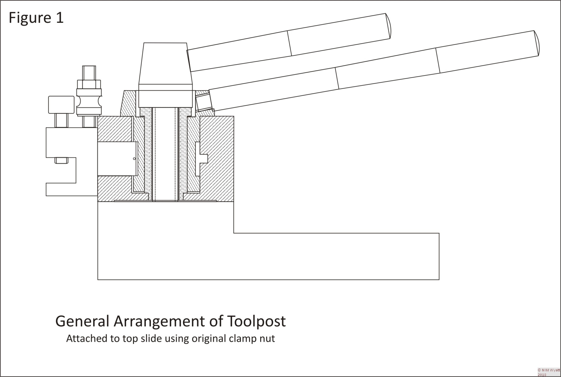
The operating principle of the toolpost may not be immediately obvious from the general arrangement (figure 1).
General Arrangement of Quick Change Toolpost
The main body (block) of the toolpost has a circular cavity in which a cylindrical cam is fitted. The cam has a hole through the middle allowing a free central pillar to be threaded onto the toolpost stud and clamped by the original lathe clamping nut. The pillar is sized to clamp only the block, so the cam, with its own handle, is free to rotate. The eccentric portion of the cam bears on two brass ‘pistons’, one in each of the dovetails on the block. Toolholders fit on these dovetails, and when the handle is used to turn the cam, it pushes on the pistons, locking the toolholders in place. Each toolholder has a setting button on top, which allows it to be removed and replaced at exactly the same height. To make using the toolpost easier, wire springs in the pistons engage with a groove in the toolpost block, so that when the cam is turned back, the pistons release automatically.
Materials
For the toolpost itself:
- Just over 1 1/4” length of 2” square bright drawn mild steel (BDMS) or continuous cast iron for Toolpost Block
- About 1 1/2” of 1 1/2” diameter round BDMS for the cam
- 2” of 5/8” diameter brass for the pistons
- 3” of springy wire about 1mm/0.04” diameter for piston springs
- 6” if 3/8” diameter BDMS for the handle
- 1 1/4” of 3/4” diameter BDMS for the pillar
For each standard or boring bar toolholder:
- 2” of 1” square BDMS
- 1 1/2” of M5 studding
- 4 M5 cap head screws
- 2” of 1/2” diameter brass
- 1 M5 nut
Note that, in practice you should allow a cutting allowance e.g. 20” of bar will make nine full-length toolholders and leave a useful offcut. Other types of toolholder may need different materials.
A final thought, for small lathes, toolposts are often made from high-strength aluminium alloys. You may wish to use such a material for the block and toolholders, especially if you have a way to get them hard anodised.
Construction
I don’t propose to give every detail of construction, but the nature of some of the parts is such that I feel it is useful to at least give a recommended approach that minimises the number of setups require. This is not exactly how I made my holder, but it is how I would make a second.
Toolpost Block
The toolpost block is made from a single piece of 2” square mild or medium carbon steel. The former is easier to machine, the latter should last a lifetime. Mount it in a 4 jaw chuck, getting it a central as possible, face off the bottom to a good finish and turn the shallow rebate. The rebate is essential to ensure the outer edges of the block make contact with the topslide, maximising grip. Now reverse the block in the chuck and face it to exact length. Drill the central hole in 2 or 3 stages. Use this hole to start your preferred boring tool to make the central 1” diameter recess, noting that it should be parallel sided with a well finished flat base. Now with a suitable recessing tool, put in the internal 1/8” groove – the centre line of the piston holes will align with this groove, so take care to get it in the right place.
The main block at the heart of the QCTP
Remove the block and mark out two faces with centres for the two piston bores. Return the block to the 4-jaw to bore and counterbore each piston hole in turn. You can drill these holes but if you are not sure of the finish your 1/2” drill leaves, then use a reamer or finish them by boring. The same recessing tool you used to cut the internal groove can be used to cut the counterbores. The depth of the counterbores is 1/8” at the shallowest point. This is to allow the rim on the pistons to move fully out of the way when fitting the cam.
We now need to cut the two dovetails. Here is the method I used, which relies on the block being a reasonably accurate 2” across. Mount the block upright in a milling vice, and zero a decent sized slot drill to the top and side of the block. Cutting a full 0.250” depth take successive cuts towards the centre until you have removed a step 0.500” long. Repeat from the other side of the block, and you should be left with a central raised area an inch wide with the piston bore at its centre. Do the same to the face with the other piston bore and check both raised steps are the same width.
To finish the dovetails, use a dovetail cutter, set to cut 0.250” down from the top surface, on one side of a step cutting in stages until the small ‘witness’ between the top face and the sloping face just disappears. Zero your DRO or handwheel index at this point. Now move to the opposite face of the step and machine the other dovetail the same way, noting the final distance reading. When you machine the second pair of dovetails start the same way, zeroing the index/DRO when you finish the first dovetail. When you machine the opposite face of this second dovetail, make sure your finishing cut is at the distance you recorded at the end of the first one. The two pairs of dovetails will now match perfectly, ensuring all your tool holders can be fitted to either of them.
An additional touch is to mill a small pocket on the underside of the block for the catch on the topslide, allowing the block to be reset correctly more rapidly. To add this, scribe a line exactly on the mid-point of the underside of the block. Now mount the block in the mill inclined backwards at 10° from the vertical. Line up a 1/2” (or similar) end mill with the scribed line and mill the pocket about 1/8” deep. The pocket should be behind the ‘front’ dovetail and be milled with the side dovetail facing down. If you are unsure – copy the pockets on the original four-way toolpost. Though I have done this on my toolpost, I am not sure how useful it is – the setting is not particularly repeatable, and unlike the four-way toolpost, you should rarely need to turn the quick release version.
Tidy up the block with fine file to remove any burrs and break the ‘arris’ on machined edges. You can draw file and then use emery paper to make the unmachined faces look a bit brighter. It is up to you if you want to paint any surfaces of the block.
Toolpost Clamp Pillar
This item (figure 3) takes the full force of the toolpost clamping nut and transfers it to the bottom of the block. If possible make it of a medium carbon steel such as EN24T, rather than plain mild steel.
The pillar is drilled clearance for the toolpost stud and is a light push fit in the hole left at the bottom of the recess in the block. Make sure the step on the end is slightly shorter than the thickness of the base of the block, so that when the toolpost clamp is tightened up it grips the block firmly in place. The length of the middle section of the pillar is a critical dimension – it should be the same as the depth of the central recess in the block. Note that this toolpost uses the existing lathe toolpost clamp (although you could make your own copy if you wish).
It is important that the clamp-screw handle points in the right direction when it is tightened up, so start by making the pillar slightly tall. If the handle points the wrong way you can face off the end a little (0.3mm off the end will allow the clamp handle to turn about 90° further).
Cam
The cam is a deceptively simple item. There is little worth in making it from medium carbon steel as the wearing surfaces are large and the impact of minor wear on the action of the cam would be negligible. The reference point for all dimensions is its top. The thickness of the upper part should be about 0.002” greater than the depth of the recess in the top – this ensures that when the pillar is locked in place by the toolpost clamp the cam will turn freely without perceptible shake.
I suggest this order or operations: In the 3-jaw chuck face off one end of the bar and drill and bore it 0.760” or greater – a very loose fit on the pillar. Now turn the outer diameter of the top part and counterbore the recess 0.377” deep. Reverse the bar and trim it to length - 1.490”. Turn the bottom section to a close push fit in the toolpost body, perhaps 0.998” and so that the length leaves the top part exactly 0.375” thick (i.e. two thou less than the depth of the recess). Move the bar to the 4-jaw chuck and offset it by 3/64” (this is not a critical dimension) and turn the offset section noting that its top and bottom edges should match with the piston holes in the block.
Now, return the bar to the three jaw in order to turn the 10-degree taper on the top section (photo 5). Do not make the tapped hole for the handle until later, or like me you will end up with an extra hole.
Pistons
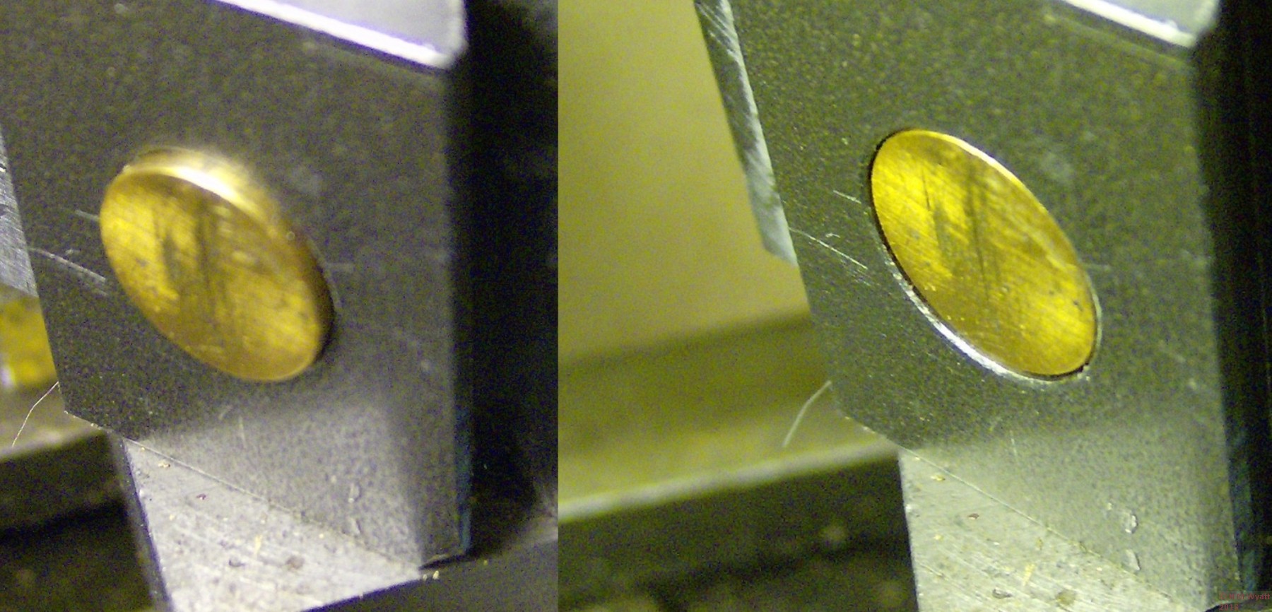
The pistons (figure 5) can be turned from 5/8” or 15mm brass rod if 9/16” is not available. Turn the main part of the pistons to a sliding fit in the block, making sure there is a good smooth finish. The flanges take no load, they only need to be big enough to stop the pistons falling right through the holes.
So you can have sprung pistons that withdraw automatically, you need to drill No.58 (this size is a loose fit for a 1mm diameter spring wire) right through. Perfection isn’t essential, but you need to be fairly accurate with this hole. A good centre pop will ensure the drill doesn’t skid, clamp the vice to the drill table and once the hole is started check the drill isn’t bending off course. Don’t forget to clear the flutes regularly – small drills clog rapidly. You now need to file flats on the piston flanges so they don’t foul the outer diameter of the cam. These can be done by eye, but ensure they are parallel with the cross-drilled hole.
The QCTP locking pistons
Try the pistons in their bores with the cam in place and make sure they are both free moving and don’t interfere with each other, aside from the desired in-out action. The pistons should be just below the surface of the dovetail when fully retracted.
Before final assembly, you should do a trial fitting of a toolholder on each dovetail in turn, to see what is the best position for the handle. At this point I suggest you make the first toolholder, at least as far as cutting the dovetail on the back of a toolholder blank, but I shall finish the description of making the toolpost before moving on to the holders.
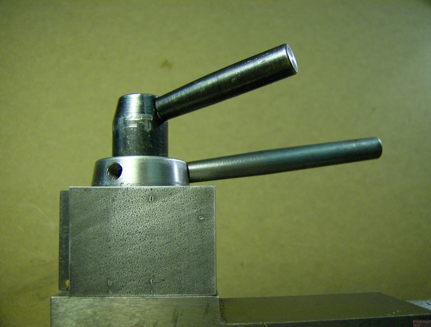
Choose the position of the handles so that they do not get in the way of fitting the toolholders when the relevant piston is retracted, and about a 90-degree turn locks the toolholder without the handle getting in the way of lathe operation. Mark the best position for the hole. Do not assume the best position without this test, or, like me, you will end up with an extra hole. If this happens, you can blank the hole with a short stub of M6 thread which will virtually disappear if carefully filed and smoothed with emery paper.
Properly fitted the handles will not interfere with each other
The hole for the handle should ideally be drilled with the cam in an angle vice at 10 degrees, but if you don’t have one, just raising one end of a normal drill vice on a block will suffice if due care is taken. Check the handle will be in the right place by fitting an ordinary M6 bolt and doing a dry run before fitting the springs.
On final assembly, fit the 1 1/14” lengths of spring wire in the cross holes. Make sure everything is clean and free of swarf, then lightly grease the pistons and fit them into their bores, aligning the springs with the groove in the block. I suggest using molybdenum-loaded or teflon grease as my experience is that these work well for parts that do not continually rotate. Grease the cam and line up the bevels on its base with the pistons, and it should be possible to insert the cam with a light click as it goes home. It will now be very difficult to take the cam back out and disassemble the toolpost. If you need to, drill and tap the pistons, say 8BA, for screws that can be used to pull them forwards so the cam can retract. The flanges will stop the pistons rotating and allow this to be done, or if you are super-cautious you can make these holes prior to parting the pistons off.
Handle
The toolpost is now complete, aside from the handle. This is simply made from a length of 3/8” bar, with an M6 thread on one end. The tapered section should be turned at about 1° (2° included angle) to match the standard mini-lathe handles. The handle can now be screwed into place, the pillar popped into the centre hole of the cam, and the toolpost fitted to the lathe.
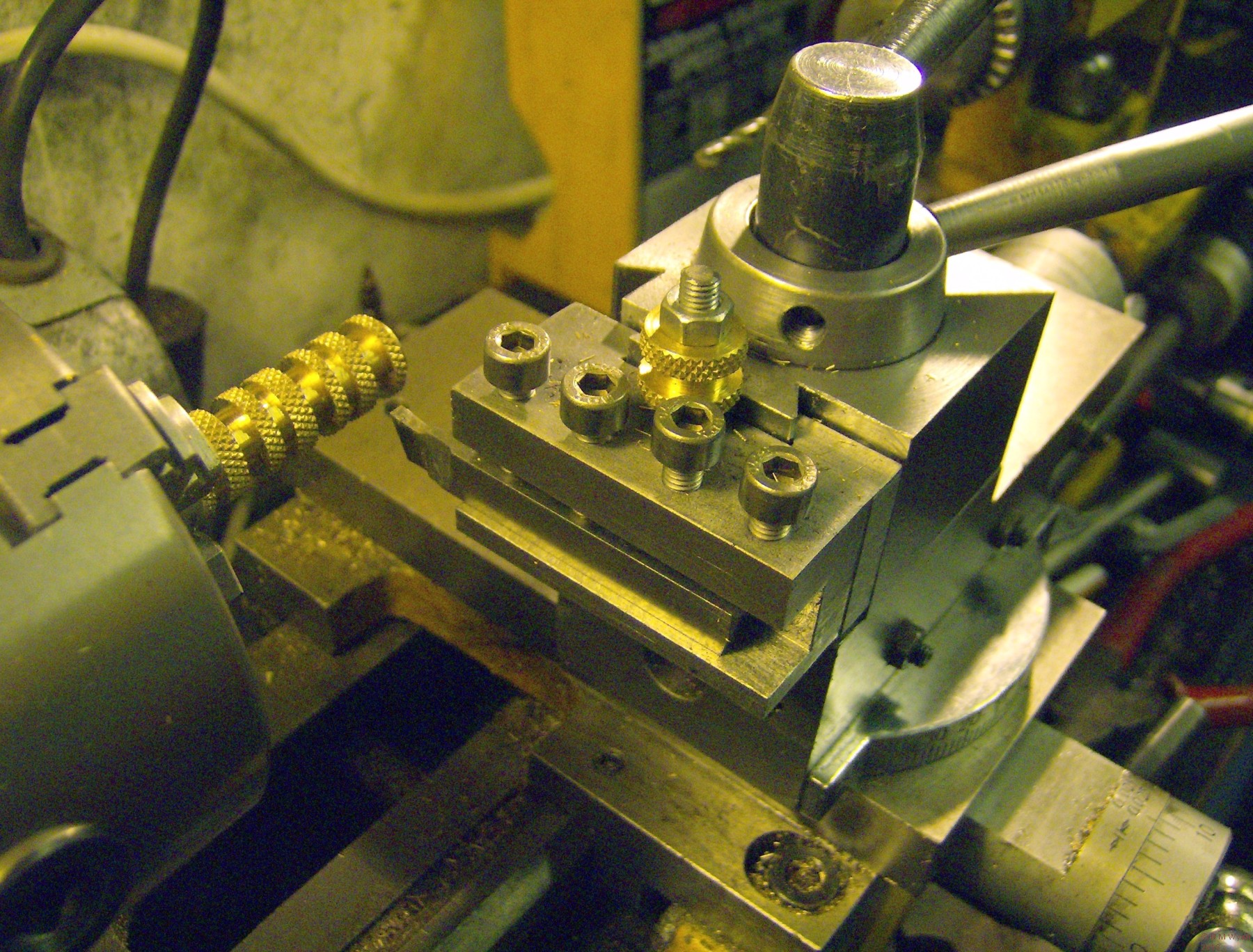
The QCTP in use
Part 2 shows you how to make a set of toolholders
You can download a free set of plans for the QCTP design with this link.
- Details
- Category: In a Model Engineer's Workshop
Of all precision tools d-bits are the ones easiest to manufacture from the scrapbox. They are the true and proper destiny for the final two inches of any self-respecting bar of silver steel.
It is possible to take the manufacture of d-bits to the level of high craftsmanship. George Thomas made a special jig to hold his d-bits while he milled them to the correct thickness. Peter Wright has a design with a reduced shank, rather like a boring tool, to ease the flow of swarf. Nevertheless, for us ordinary mortals the simplest of designs will work.
A d-bit cuts only on its end. The name comes from the cross section of the tool, which must be marginally more than a semicircle to ensure that it does not cut on its edges. Because the d-bit cuts its own precision guide as it goes, it makes accurate sized holes with a good surface finish. Many writers claim that a d-bit will produce better results than a reamer, which is not bad considering that they cost a few pence to make.
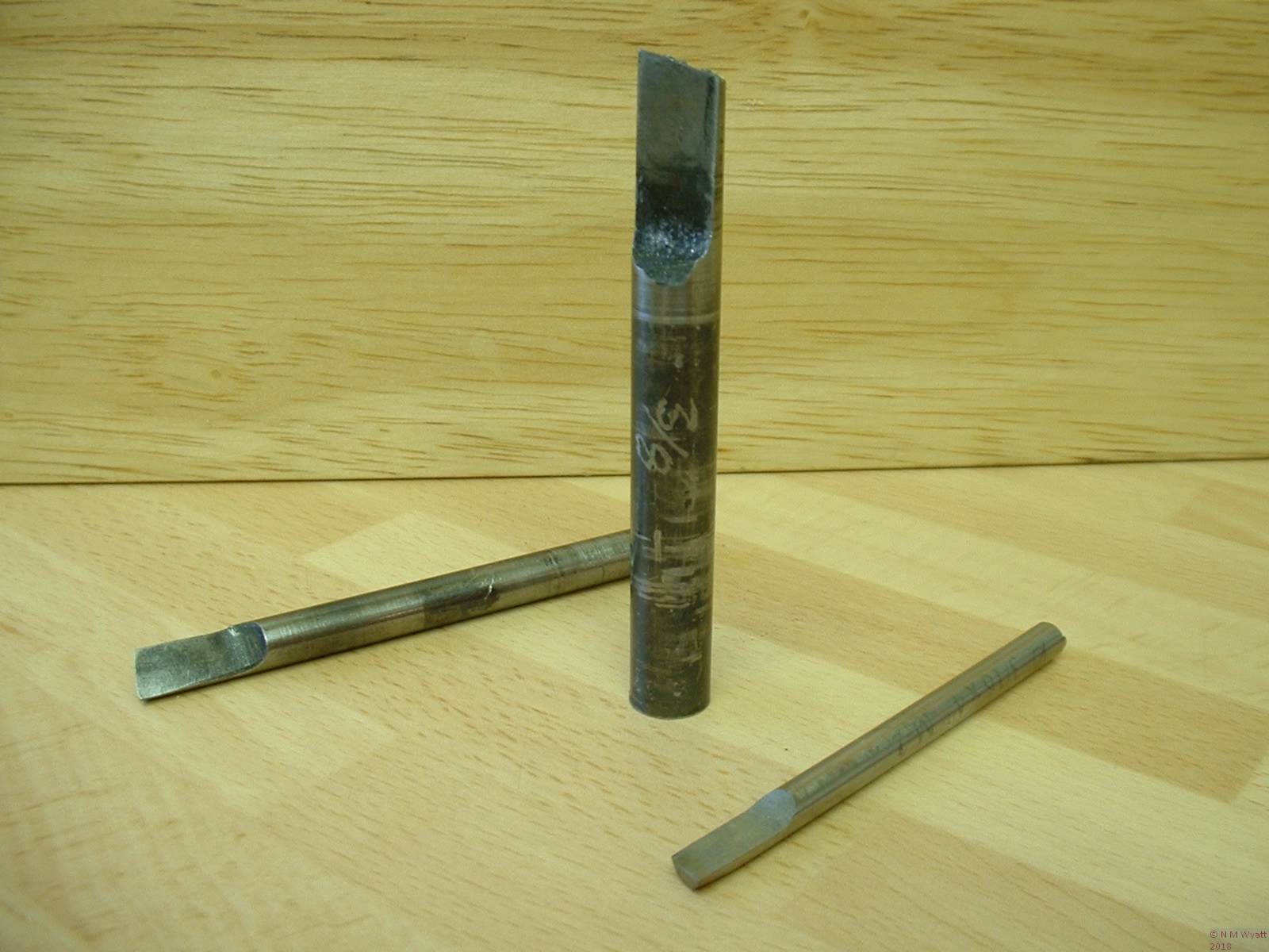
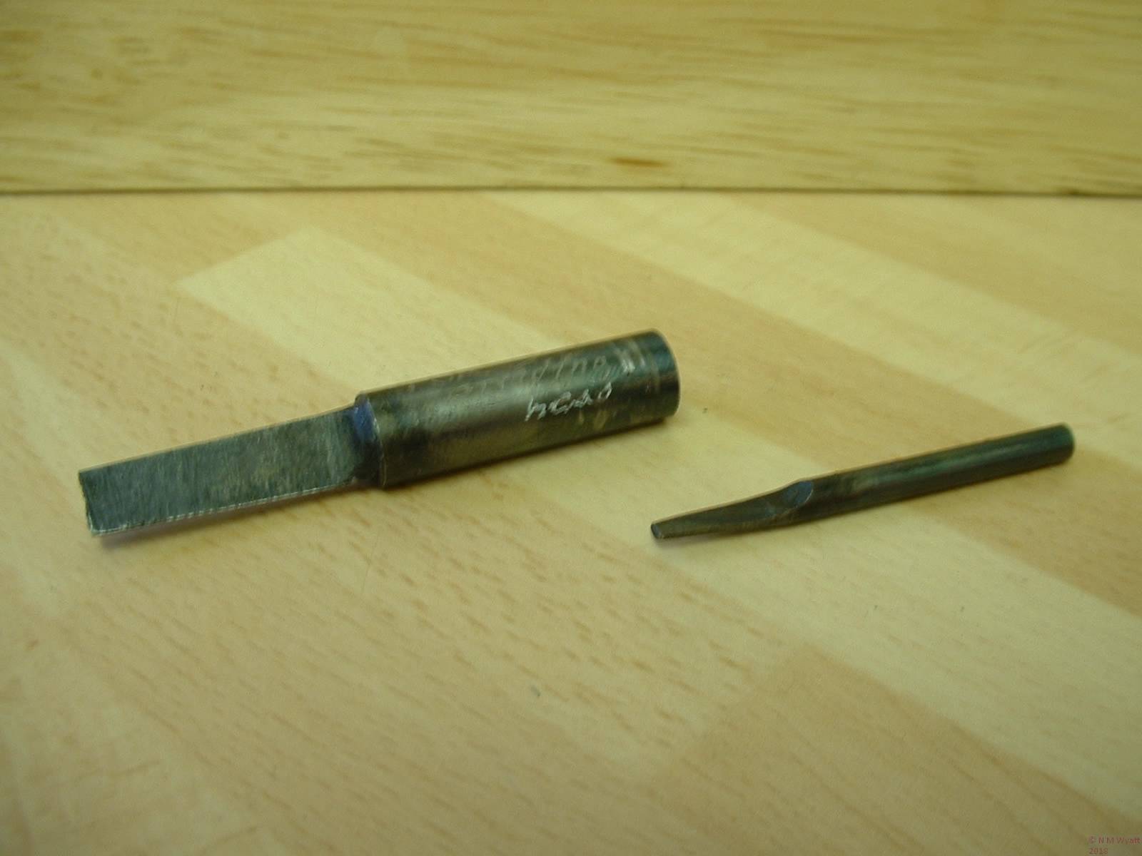
A selection of home-made d-bits
Manufacture is straightforward, simply grind, mill or file away a few thou less than half of the diameter of a piece of round silver steel. Shape the end of the bar to provide clearance and form the cutting edge. An angle right across the end cuts a little more freely, but if the end is partially straight it will allow you to finish holes with a square bottom.
The tool should be hardened by heating to a good red heat , then quench it end-first in clean water, with a gentle stirring action. Don’t just grab it with pliers, and shake it around in the water if it is of thick section it may well crack or distort (how do I know?) Don’t worry about soak-heating the tool as it is not critical to harden it to the core, indeed prolonged heating will burn out the vital carbon from the
cutting edges and diminish its hardenability. If you coat the tool in washing up liquid first it will be easier to clean it up, using wire wool or scotchbrite.
The tool will now be glass hard, brittle enough to shatter if dropped on a hard surface, (yes, it has happened to me). To temper it, apply gentle heat to the shank until the metal starts to form a coloured oxide film. The colours will run down the shank to the tip, and just as a ‘dark straw’ colour reaches the end, quench the tool again. Finally put a good finish on the end and the flat side of the bit with a slip stone – do not take any metal off the curved surface.
As it has no top rake heavy cuts are out and a d-bit is best used to finish a pre-existing hole. It does no harm if a short pilot the same nominal diameter as the bit is made to get everything off to a good start. Beware overheating the tip, as this will draw its temper and it will rapidly become blunt. The secret is to keep the speed modest and use plenty of lubricant. Swarf soon builds up on the face of the tool, so regularly withdraw it, and slap on a dab of cutting oil.
You can make d-bits for other purposes as well. Tapered d-bits can make accurate tapered holes. Turn up a handful of matching taper plugs with the lathe at the same setting, and they can be used to make taper cocks. A round ended d-bit can be used to make round sockets and rivet sets. One which is flat across the end can be used to cut or renew valve seats.
D-bit style taper reamers
One final thought – the so-called toolmaker’s reamer is an even simpler tool. In this case the blank is cut across at about 20°, hardened, tempered and stoned to a good finish. Less robust than a d-bit, such reamers will take a very accurate final skim from an undersize hole.
- Details
- Category: In a Model Engineer's Workshop
Looking back through literally hundreds of model engineering magazines, few things have exercised writers more than describing how to judge the hardening temperature for silver steel.
The fashion is to compare this to various food items – notably cherries or boiled carrots. The Japanese swordmakers would heat their work to the colour of the setting sun, just touching the horizon, and that rich orange-red colour – where the light seems almost to come from just under the surface is what I aim for. But the truth is that colours are subjective, and until you know what works for you, you will never be sure. So here is how to be SURE you have the right temperature.
Keep a magnet to hand, and a pair of pliers. As the metal starts to glow, offer it up to the magnet. If the magnet jumps up to the hot metal, quickly remove it with the pliers and heat the metal some more. When the structure of the steel changes to its harder form, the same change will also cause it to lose any attraction for the magnet. Take a good look – whatever colour red it is now is the right one for hardening.
If hardening silver steel you are supposed hold it at this temperature for five minutes for every quarter inch of thickness. If you don't 'soak' the metal for this long, it may not harden right through - in most cases this is not a bad thing, as it means the object will be less brittle, so I rarely keep the work hot for more than five minutes, however thick it is.
A last thought, gauge plate often requires a higher temperature - but the magnet test will still work.
So which of these colours is 'cherry red'?
- Details
- Category: In a Model Engineer's Workshop
A fly cutter is a single point tool, usually used for machining plane surfaces. It is an inherently accurate tool when used in this way, and if the toolbit is a good one, rigidly held, it will produce smooth, flat surfaces with the most basic of set ups - as long as the mill is correctly trammed (i.e. the column is at right angles to the table). It is also possible to flycut convex surfaces, but the lack of fine adjustment of the typical flycutter imposes limits on accuracy.
There are innumerable ways of making a fly cutter. The basic requirement is simply a toolbit holder, which is easy to attach to a rotary machine such as a lathe or a mill. This straightforward but useful example was inspired by a photo, though many similar ones are manufactured. Stan Bray has described another useful style, which bolts directly to the faceplate. Tubal Cain was unashamedly used a square-section boring bar held crosswise in a chuck!
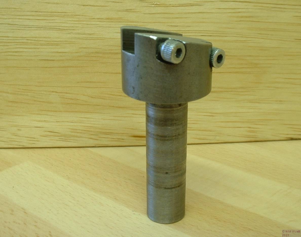
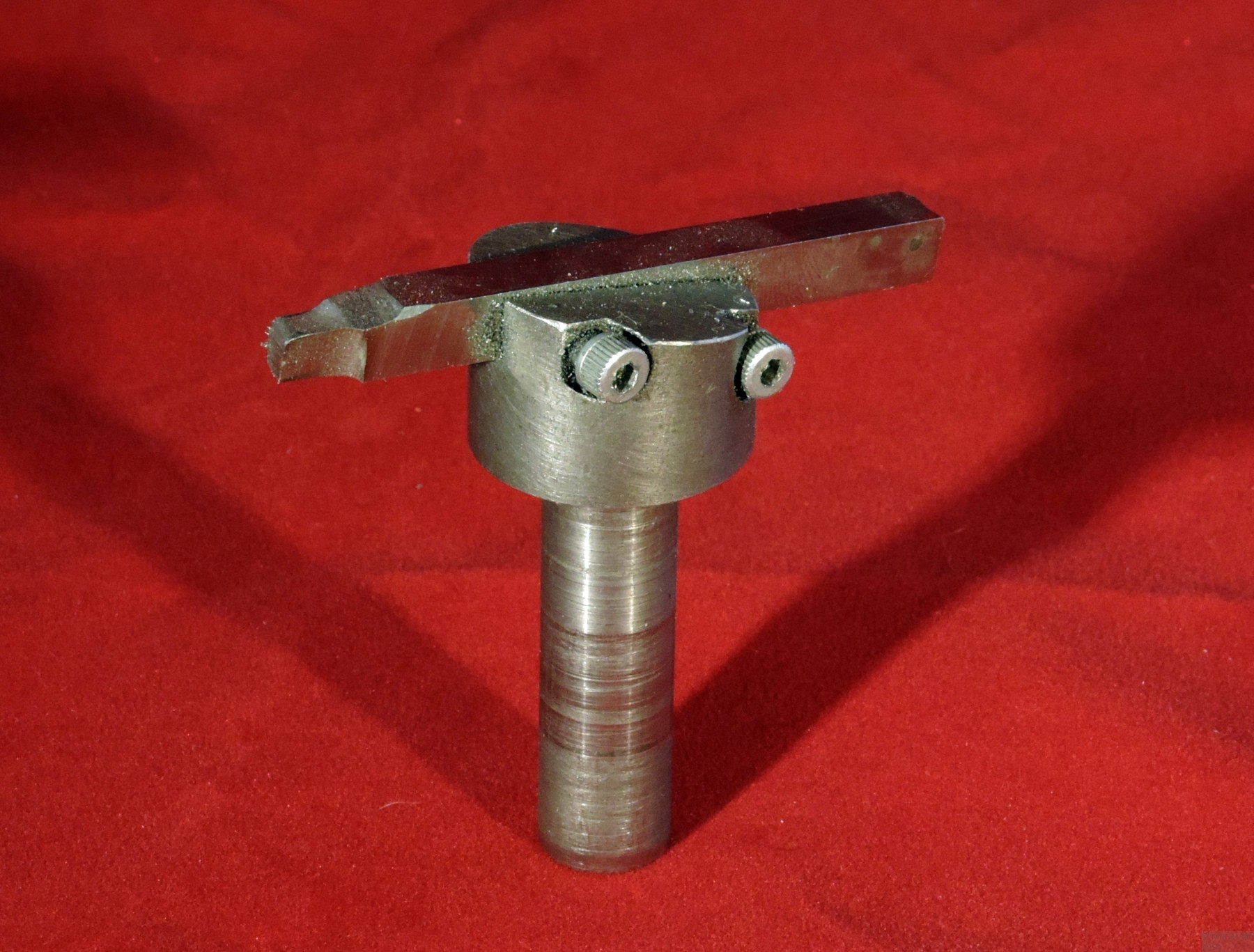
The body of the cutter is just a piece of 1” mild steel bar, turned down to 1/2” to make a shank. When you hold the cutter in a chuck, the body can be held flush against the jaws, preventing any rearward movement. The thick end of the bar can be sawn and then filed to a 10° angle. This angle gives the toolbit its top relief.
For use with 1/4” HSS tool steel, a slot offset from the centre line of the body is needed. On my mini-lathe I was able to achieve this by holding the shank in the lathe’s tool holder, suitably angled. I cut the slot with a 1/4” FC3 mini-mill, which gave a slot that was good fit for the tool steel. By using the same mill in a pillar drill and ‘plunging’ it into the thick side of the body, two recesses with 4BA tapped holes for the securing screws were easily made.
A simple Fly Cutter
The tricky bit is making a good toolbit. You will need a roughly 2” long piece of 1/4” square HSS. If you need to shorten a longer piece, grind a shallow groove all round with a mini-drill and carborundum wheel. Hold the bar in a vice, covered with a cloth, then tap the end sharply with a hammer. To visualise the shape of the tool, think how it will contact the work as it rotates; with the bit in the holder identify the corner that will do the cutting. The angle of the holder provides one clearance angle, but you need to grind further clearance on the end, ‘front’ and ‘top’ of the bar. Aim for 5-10°, and a little more on the end of the bar. Effectively you need to create a left-handed knife tool.
In use the cutter should be held firmly in a chuck. In the case of milling machines supplied with heavy-duty drill chucks, you can probably get away with holding the cutter in it, but don’t try using the fly cutter in a pillar drill. Fly cutters need to be run slowly; this one has a maximum of a 3” cut and you should run it no faster than you would turn a 6” diameter cylinder - pretty slowly. The work should be moved past the cutter; on smaller lathes it can be a challenge to achieve a set-up where the whole area to be worked passes the cutter. The depth of cut and feedrate should be less than usual, because of the significant leverage between the end of the cutter and the shank. Be patient and keep your cutters sharp and you will get excellent results.
Finally, a version of this tool that is not angled can be used to hold form tools, such as those used for cutting gearteeth or special profiles.
The finished fly cutter fitted with a toolbit
- Details
- Category: In a Model Engineer's Workshop
I asked someone to search me out a cheap aneroid barometer to calibrate an electronic barometer I was testing. They rang that day with a tale of various ‘pressure meters’, I said go for it, and it turned out that they did rather well. In a series of tins and boxes they presented me with two working barometers, a third with no needle and a whole host of barometer spares, all virtually given away with that wonderful British sentiment ‘they would go to someone who wants them’. There was also the, very grubby, internal mechanism from a large pressure gauge, probably 4” in diameter. Initially I thought this may have been from a full size steam engine, but it appears to read only to about 20psi, so who knows what its original purpose was?
Along with all these rather tatty but useful bits and pieces, was another gauge that had been polished up and mounted on a stand made from a piece of hardwood. Advised by a bystander that it was rather old and a good deal, the price was £5 for this object.
It took me a double-take to be sure exactly what this object was. At a glance it was a large pressure gauge, on inspection it was compound gauge, measuring vacuum and pressure. Better still, it was a genuine “Bourdon Compound Gauge” – a fine instrument and possibly one made in the days of Monsieur Bourdon himself!
Eugene Bourdon's Patent Compound Gauge
Patented by Eugene Bourdon in 1849, the Bourdon Gauge is a familiar instrument to model engineers, most usually encountered as a means of measuring steam or air pressure. The working principle is simple – a curved pipe, usually of a thin, springy material such as hard brass or beryllium copper, unrolls slightly when pressurised (like the feathered toys found in Christmas crackers!) This movement is amplified by a rod and lever, and, with better quality gauges, passed to the indicator needle via a pinion and a sector of a gear. Bourdon gauges can also be arranged to read vacuum relative to ambient pressure, and, if the mid point of the scale is carefully chosen pressures above or below ambient may be measured.
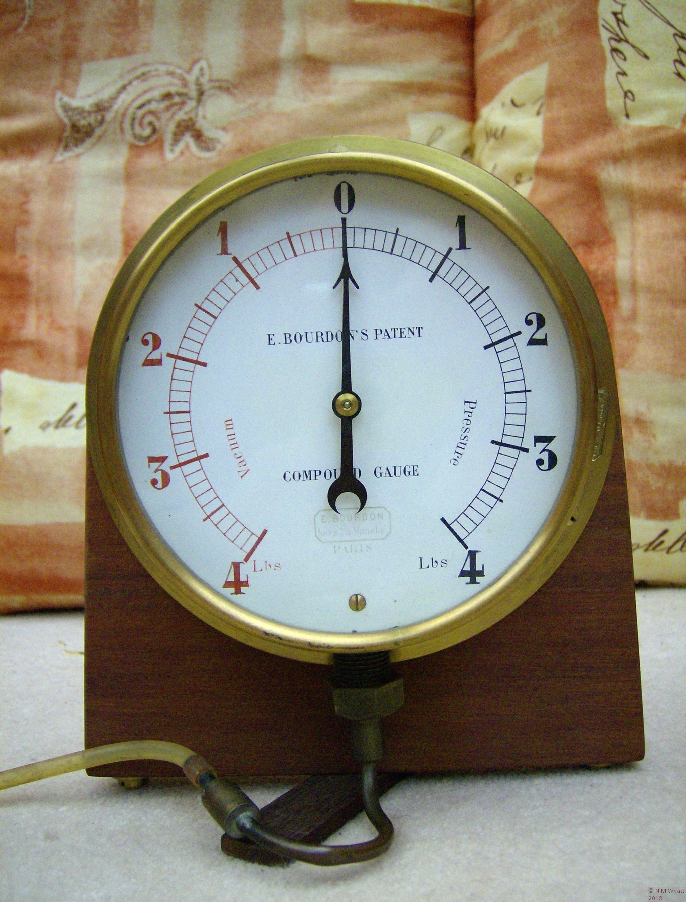
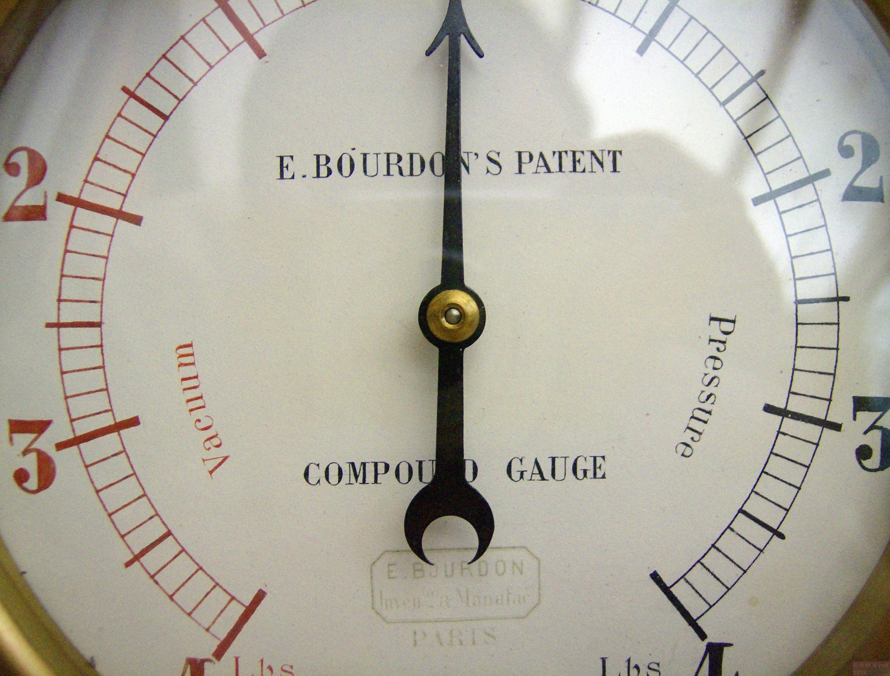
Such a gauge, measuring both pressure and vacuum, is a ‘compound gauge’, and mine was an example of this, reading +/- 4 pounds (presumably per square inch), subdivided to tenths of an inch. 4 psi is 276 millibars or rather more than a quarter of an atmosphere.
The gauge is housed in a heavy, circular brass case, 5” in diameter and 2” deep with a flange 6 1/2” across. A bezel holds in place a glass that is clear and without blemishes, but lightly rippled, suggesting that it is original old glass predating modern float glass. At the bottom of the circular case is a large thread, on which a nutted union fits, this appears to be original and contains a rather worn fabric washer. The union joins to a bent brass tube with a soft-soldered brass piece on the end, which appears to have provided a spigot for attaching a rubber tube.
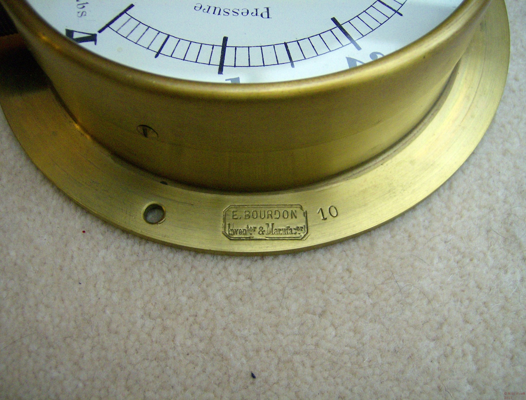
The dial of the gauge is beautifully hand-figured in red (vacuum) and black (pressure) ink. In impeccable hand lettering the dial is also marked “E. BOURDON’S PATENT COMPOUND GAUGE”. Beneath this is stamped the maker’s mark “E. BOURDON Inventor & Manufac.or PARIS”. This mark is repeated, with only minor differences as a deep stamping in the rim of the brass case. Adjacent to this mark is the stamped number 10, probably not a serial number, it may relate to a calibration record. The case itself, and its bezel, appear to have been turned from brass castings. The finish is either very fine turned or finished with emery – not a polished appearance.
Markings on the dial
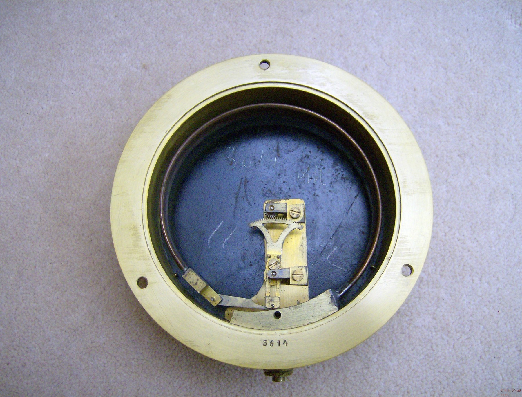
On removing the gauge from its plinth a black steel backplate is revealed (which may have been repainted), along with the serial number 3614 stamped into the case. On removing the backplate the mechanism is revealed, together with, scratched into the back of the dial, the serial number 3614 once again and the initials AM. These are both in a bold and, to my eye, continental hand. There are also the figures 11 and 2 marked in a more casual hand. The mechanism itself is pinned and screwed together. Interestingly the lever is made adjustable in length. Presumably the screw allowed calibration to be carried out before the two parts of the lever were finally pinned together. Aside from steel pivots and the copper(?) Bourdon Tube itself, all parts are brass and not highly finished.
Inside the case
An interesting touch that can just be seen in the photograph is that the end teeth of the gear sector that turns the pinion have been bent inwards. A crude but effective way of ensuring that over or under pressure can’t run the pinion off the end of the sector.
My limited lungpower can drop the vacuum to the full 4”, but only raise 1” of pressure. The reading appears accurate compared to a good quality but less sensitive modern gauge. It only reads correctly when the gauge is vertical; lying it down introduces an error of 1/2” of pressure, which illustrates how sensitive an instrument it is. Whilst ideal for demonstrating that a model engine can run on the merest whiff of air pressure, the gauge is far too sensitive for use on a working steam engine. It seems to me that this is a laboratory instrument of some class. Perhaps it was rescued from a school or university laboratory during the days when any useful, educational or interesting equipment was liable to end up in a skip, and mounted on its wooden plinth by appreciative hands?
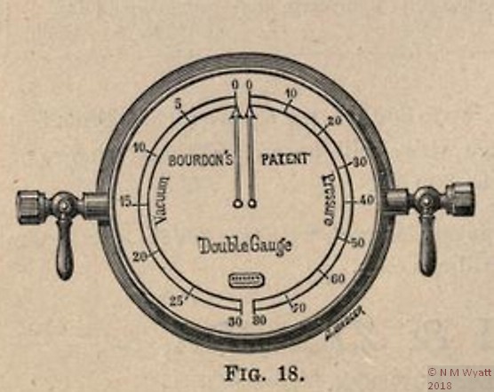
I was surprised by how difficult it is to find out more about Monsieur E. Bourdon and his invention, despite the fact that there are now millions in use across the globe. Eventually, I was directed to a 1887 Negretti and Zambra catalogue which showed the same maker's stamp and embossing on the gauge.'Purchasers are desired to examine and compare M. Bourdon's Gauges. They will find the works to be constructed and finished like a watch, whilst the majority of imitations are put together ROUGH FROM THE CASTINGS, consequently liable to adhere and give erroneous indications'.
Bourdon's Patent Double Gauge in an 1887 catalogue
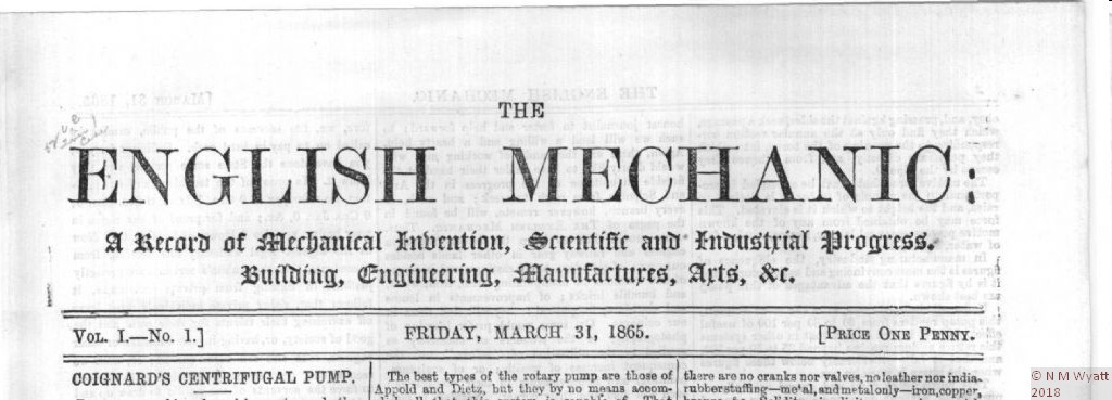
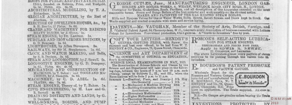
A second source gave images showing the mark in an 1865 issue of The English Mechanic. It seems that the gauge would have come out of M. Bourdon's workshop some time between 1850 and 1890, if you can help with dating from the serial number, please get in touch.
The English Mechanic, March 31 1865
The Maker's Mark in the text...
... and on the case
I contacted the Science Museum, whose expert stated he can's remember seeing one in such good condition. They already hold another gauge presented by M. Bourdon himself in their Motive Power collection (inv. 1877-450).
So, it seems this gauge is rather special but best of all at over 150 years old, it still has a job of work to do from time to time. I hope this article makes it easier for anyone else with a similar gauge to find out its history.
- Details
- Category: In a Model Engineer's Workshop
Subcategories
Reference Information Article Count: 5
This is a repository for all sorts of workshop data and background information.
Page 2 of 3

